 |
| Place of Origin: | China |
| Brand Name: | Kacise |
| Certification: | CE |
| Model Number: | KBU601 |
| Minimum Order Quantity: | 0-100 |
|---|---|
| Price: | Negotiable |
| Packaging Details: | each unit has individual box and all boxes are packed in standard packages or customers requests available |
| Delivery Time: | 5-8 working days |
| Payment Terms: | L/C, D/A, D/P, T/T, Western Union, MoneyGram, Paypal |
| Supply Ability: | 100 |
| Signal Output: | RS-485 (Modbus/RTU Protocol) | Measuring Range: | 0~14pH |
|---|---|---|---|
| Temperature Range: | 0 ~ 65℃ | Work Pressure: | <0.2MPa |
| Power Consumption: | <0.5W | Ip Grade: | IP68 |
| Power Supply: | 12~24VDC ±10% | Wetted Part Material: | PPR |
| High Light: | water turbidity sensor,oil in water sensor |
||
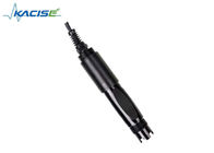
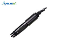
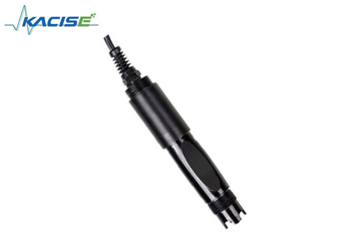
HACH KWS-700 Online pH Sensor
Introduction
KWS-700 online pH sensor is used in environmental water quality monitoring, acid/alkali/salt solution, chemical reaction process, industrial production process, it can meet the requirements of online pH measurement for most industrial applications.
| Model | KWS-700 |
| Measuring Range | 0~14pH |
| Accuracy | ±0.1pH |
| Resolution | 0.01pH |
| Temperature Range | 0 ~ 65℃ |
| Work Pressure | <0.2MPa |
| Temperature Compensation | automatic temperature compensation |
| Output | RS-485, MODBUS protocol |
| Power Supply | 12~24VDC ±10% |
| Wetted Part Material | PPR |
| Installation | Immersion mounting, 3/4 NPT thread |
| Cable Length | 5 m, customizable |
| Calibration Method | Two-point calibration |
| Power Consumption | <0.5W |
| Ip Grade | IP68 |
Dimension
![]()
Installation and Electrical Connection
Installation
![]()
Note: The sensor should not be installed upside down or horizontally when installed, at least at an angle of 15 degrees or more.
Cable specification: Considering that the cable is immersed in water (including sea water) for a long time or exposed to the air, the cable has certain corrosion resistance. The outer diameter of the cable is Φ6 mm and all interfaces are waterproof.
Maintenance
Use and maintenance
When measuring the pH sensor, it should be cleaned in distilled water (or deionized water), and the filter paper should be used to absorb moisture to prevent impurities from being introduced into the liquid to be tested. 1/3 of the sensor should be inserted into the solution to be tested.
The sensor should be washed when not in use, inserted into a protective sleeve with a 3.5 mol/L potassium chloride solution, or the sensor inserted into a container with a 3.5 mol/L
potassium chloride solution.
Check if the terminal is dry. If it is stained, wipe it with absolute alcohol and dry it. Avoid long-term immersion in distilled water or protein solution and prevent contact with silicone grease. With a longer sensor, its glass film may become translucent or with deposits, which can be washed with dilute hydrochloric acid and rinsed with water. The sensor is used for a long time. When a measurement error occurs, it must be calibrated with the meter for calibration.
When the calibration and measurement cannot be performed while the sensor is being maintained and maintained in the above manner, the sensor has failed. Please replace
the sensor.
Standard Buffer Ph Reference Table
| Temp(°C ) | 4.00 | 4.01 | 6.86 | 7.00 | 9.18 | 10.01 |
| 0 | 4.00 | 4.00 | 6.98 | 7.12 | 9.46 | 10.32 |
| 5 | 4.00 | 4.00 | 6.95 | 7.09 | 9.39 | 10.25 |
| 10 | 4.00 | 4.00 | 6.92 | 7.06 | 9.33 | 10.18 |
| 15 | 4.00 | 4.00 | 6.90 | 7.04 | 9.28 | 10.12 |
| 20 | 4.00 | 4.00 | 6.88 | 7.02 | 9.23 | 10.06 |
| 25 | 4.00 | 4.01 | 6.86 | 7.00 | 9.18 | 10.01 |
| 30 | 4.01 | 4.02 | 6.85 | 6.99 | 9.14 | 9.97 |
| 35 | 4.02 | 4.02 | 6.84 | 6.98 | 9.17 | 9.93 |
| 40 | 4.03 | 4.04 | 6.84 | 6.97 | 9.07 | 9.89 |
| 45 | 4.04 | 4.0 5 | 6.83 | 6.97 | 9.04 | 9.86 |
| 50 | 4.06 | 4.06 | 6.83 | 6.97 | 9.02 | 9.83 |
Service commitment
The company provides local after-sales service within one year from the date of sale, but does not include damage caused by improper use. If repair or adjustment is required, please return it, but the shipping cost must be conceited. Damaged on the way, the company will repair the damage of the instrument for free.
|
Register Address |
Name | Description |
Number Of Registers |
Interview Method |
|
40001
(0x0000) |
Measured value
+temperature |
4 double-byte integers, which are the measured value, the measured number of decimal places, the temperature value, and the decimal value of the temperature value. |
4 ( 8 bytes) |
read |
|
44097
(0x1000) |
Zero calibration |
Calibrated in a standard solution with a pH of 6.86, writing data to 0 |
1 ( 2 bytes) |
write |
|
44099
(0x1002) |
Slope calibration
(4pH) |
Calibrated in a standard solution with a pH of 4.00, writing data to 0 |
1 ( 2 bytes) | write |
|
44101
(0x1004) |
Slope calibration
(9.18pH) |
Calibrated in a standard solution with a pH of 9.18, writing data to |
1 ( 2 bytes) | write |
|
44103
(0x1006) |
Zero calibration value |
The data is read out as a zero offset. |
1 ( 2 bytes) | read |
|
44105
(0x1008) |
Slope calibration value |
The read data is the slope value x1000 . |
1 ( 2 bytes) | read |
|
44113
(0x1010) |
Temperature calibration |
Calibrated in solution, the data written is the actual temperature value x10 ; the read data is the temperature calibration offset x10 . |
1 ( 2 bytes) | Write /read |
|
48195
(0x2002) |
Sensor address |
The default is 6 and the data range is 1-127 . |
1 ( 2 bytes) | Write /read |
|
48225
(0x2020) |
Reset sensor |
The calibration value is restored to the default value and the write data is 0. Note: the sensor needs to be calibrated again after resetting. |
1 ( 2 bytes) | write |
a) Read data instruction
Function: Obtain the pH and temperature of the measuring probe; the unit of pH is pH; the unit of temperature is °C.
Request frame: 06 03 00 00 00 04 45 BE ;
Response frame: 06 03 08 00 62 00 02 01 01 00 01 24 59
Example of reading:
| pH value | Temperature value |
| 00 62 00 02 | 01 01 00 01 |
pH: 00 62 indicates the hexadecimal reading pH value, 00 02 indicates that the pH value has 2 decimal places and is converted to a decimal value of 0.98 .
Temperature value: 01 01 indicates the hexadecimal reading temperature value, 00 01 indicates that the temperature value has 1 decimal place and is converted to a decimal value of 25.7
b) Calibration instructions:
Zero calibration
Function: Set the pH zero calibration value of the electrode. The zero value is based on the 6.86 pH standard. The examples are as follows;
Request frame: 06 06 10 00 00 00 8C BD
Response frame: 06 06 10 00 00 00 8C BD Slope calibration
Function: Set the pH slope calibration value of the electrode; the slope calibration is divided into high point and low point calibration, and the alkaline solution is measured at the high point; the acidic solution is measured at the low point, where the standard solution is high here. point 9.18pH, low 4.00pH standard solution of the calibration reference, examples are as follows:
High point standard solution 9.18 pH calibration: Request frame: 06 06 10 04 00 00 CD 7C
Response frame: 06 06 10 04 00 00 CD 7C Low standard solution 4.00 pH calibration: Request frame: 06 06 10 02 00 00 2D 7D
Response frame: 06 06 10 02 00 00 2D 7D
c) Set the device ID address:
Role: set the MODBUS device address of the electrode; Change the device address 06 to 01. The example is as follows Request frame: 06 06 20 02 00 01 E3 BD
Response frame: 06 06 20 02 00 01 E3 BD
5. Error response
If the sensor does not execute the host command correctly, it will return the following format information:
| Definition | address | function code | CODE | CRC check |
| data | ADDR | COM+80H | Xx | CRC 16 |
| Number of bytes |
1 |
1 |
1 |
2 |
a) CODE : 01 – function code error
03 – data is wrong
b) COM : Received function code
Field application example
![]()
Contact Person: Ms. Evelyn Wang
Tel: +86 17719566736
Fax: 86--17719566736
Address: i City, No11, TangYan South road, Yanta District, Xi'an,Shaanxi,China.
Factory Address:i City, No11, TangYan South road, Yanta District, Xi'an,Shaanxi,China.