 |
| Place of Origin: | CHINA |
| Brand Name: | kacise |
| Certification: | CE,FDA |
| Model Number: | KWS-901 |
| Minimum Order Quantity: | 10-1000 |
|---|---|
| Price: | $100-$2000 |
| Packaging Details: | Common package or custom package |
| Delivery Time: | 10-15 days |
| Payment Terms: | L/C, D/A, D/P, T/T, Western Union, MoneyGram |
| Supply Ability: | 2000pcs/day |
| Name: | Low-Range Turbidity Sensor | Range: | 0~10NTU |
|---|---|---|---|
| Accuracy: | 0.01NTU Or ±2% (Take The Bigger One) | Resolution: | 0.001NTU |
| Light Source: | LED | Power Dissipation 0.6W(Brush Close)、1W(Brush Working): | 0.6W(Brush Close)、1W(Brush Working) |
| Power: | DC 12~24V,1A | Flow Range: | 180~500mL/min |
| Temperature Range: | 0~50℃ | Sensor Size: | Φ54.6mm*193.5mm |
| Inlet Pipe: | 2 Points PE Pipe | Drain Pipe: | 3 Points PE Pipe |
| Output: | Modbus RS485 | Maintain: | Self-cleaning Wiper |
| Body Material: | Water Channel:PC+ABS Sensor:316L+POM | ||
| High Light: | 0-50 degrees Water quality sensors,industrial Manufacturing Water quality sensors,Aquaculture Water quality sensors |
||
1. Introduction
Low-Range Turbidimeter is for drinking water quality online monitoring, with ultra-low
turbidity detection limit, high precision measurement. The equipment has the characteristics
of a long time without maintenance, water-saving work, and digital output. It supports remote
data monitoring on cloud platforms and mobile phones, and RS485-Modbus communication. It
can be widely used in the online monitoring of turbidity of tap water, secondary water supply,
pipe network terminal water, direct drinking water, membrane filtered water, swimming pool, and surface water.
2. Feature
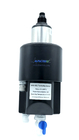
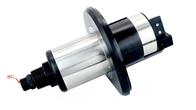
3. Sensor size diagram
![]()
![]()
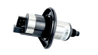
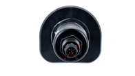
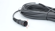
4. Cable definition
4 wire AWG-24 or AWG-26 shielding wire. OD=5.5mm
![]()
1, Red—Power (VCC)
2, White—485 Date_B ( 485_B)
3, Green—485 Date_A (485_A)
4, Black—Ground (GND)
5, Bare wire—shield
5. Technical Specifications
| Name | Low-Range Turbidity Sensor |
| Range | 0~10NTU |
| Accuracy | 0.01NTU or ±2% (Take the bigger one) |
| Resolution | 0.001NTU |
| Light Source | LED |
| Power Dissipation | 0.6W(Brush close),1W(Brush working) |
| Power | DC 12~24V,1A |
| Flow Range | 180~500mL/min |
| Temperature Range | 0~50℃ |
| Sensor Size | Φ54.6mm*193.5mm |
| Inlet Pipe | 2 Points PE Pipe |
| Drain pipe | 3 Points PE Pipe |
| Output | Modbus RS485 |
| maintain | Self-cleaning Wiper |
| Body material |
Water channel: PC+ABS Sensor:316L+POM |
Note:
1. The above technical parameters are all data under a standard liquid environment.
2. Sensor life and maintenance calibration frequency are related to actual field conditions.
6. Installation and equipment operation
6.1 Configuration table
| Standard configuration | Number | Remarks |
| Low-Range Turbidimeter | 1 | |
| Flow cell | 1 | |
| Mounting plate | 1 | |
| Water inlet hose/Drain hose/overflow | 3 | |
| Flow regulating device | 1 | |
| Cable | 1 | 10m |
| Transmitter | 1 | Options (not standard) |
6.2Installation Instructions
6.2.1Fixed Installation
Select the installation method shown in Figure (a) or Figure (b) to fix the midplane based on the
actual installation environment.
![]()
![]()
![]() (a)Wall installation diagram (b) backplane installation diagram (c)Size dimension of the mounting plate
(a)Wall installation diagram (b) backplane installation diagram (c)Size dimension of the mounting plate
6.2.2 Installation precautions
① Ensure that the backplane is securely installed;
② Please ensure that the circulation slot is securely clamped;
③ Please ensure that the water inlet, overflow, and sewage pipes are stuck in place, And Two
points, Three points blue clasp clip to the position to avoid leakage.
④ Special attention: The manual drain valve should be kept closed and only opened for cleaning
and closed afterward.
6.3 Water supply
(1)Drain water
Open the inlet switch, check and adjust the "flow regulating device", so that the inlet flow rate is
kept within the range of the index requirements;
Confirm that the manual valve of the sewage outlet is closed, open the upper cover of the flow
tank, and observe whether there is starting flow in the follicle device. If there is running water, it
is normal, and if there is no running water or the flow rate is very slow, check whether the inlet
water and flow regulating device are set normally.
(2)Check the water storage function
Open the top cover, and the chamber of the cylinder in the middle of the flow pool is the water
storage and measurement pool. Check whether the water is stored normally and the liquid level
rises slowly until it spills out from the remaining mouth. At the same time, check whether there
are impurities and residues in the measurement pool with the help of lighting equipment such as
a flashlight, If there are impurities, discharge or remove them before storing water again.
(3)Install turbidity probe
Insert the turbidity sensor into the upper cover and screw it into the upper cover card slot, then
insert the whole into the flow pool and make the upper cover close to the flow pool cover.
(4)Power up
After completing the above process, the sensor can be powered on and measured by the acquisition
protocol, transmitter, etc.
![]()
6.4 Calibration
The turbidity sensor can be installed and used directly, and the second calibration is not required
for the first installation. If the customer needs it or the data offset is found in the later
maintenance, our company suggests using tap water as the water sample for single-point
calibration and the calibration parameters can be written through our host computer or in the
form of communication protocol register.
7. Maintenance schedule and methods
7.1Maintenance cycle
| Maintenance task | Recommended maintenance frequency |
| Sensor cleaning | Every month |
| Calibration sensor | Every 1~2months, According to the situation of use |
| Flow cell cleaning | Every 1~2months, According to the situation of use |
| Replace the cleaning brush | Every 6 months |
Cleanliness is very important for maintaining accurate readings.
7.1.1 Confirm that the power supply is normal
The supply voltage is DC, the voltage value is DC12-24V, and the voltage is stable
7.1.2 Confirm the incoming water is normal
There is water from the pipe;
Incoming water can flow into the circulation tank;
No water overflow at the inlet of the circulation tank.
7.1.3 Check for smooth drainage
Based on determining that the incoming water is normal, the liquid level of the circulation
tank is normal and there is no water overflow:
Inspection equipment (backplane, backplane, internal circulation trough) whether there is water,
if there is water, that existed before the water situation, the causes of this phenomenon have two,
one is the water pressure, water directly from the circulation tank overflows, second, poor
drainage, causing water to spill from the circulation tank, if we can rule out water pressure is too
large, poor drainage.
7.2 Probe Maintenance
7.2.1 Clean sensor
Power off the meter, remove the sensor from the flow slot and clean the sensor.
When cleaning a light hole, you need to clean it with a cotton swab, preferably using a cotton
swab dipped in alcohol. If there is no alcohol on site, use a dry cotton swab, if not, use a paper
towel.
7.2.2 Check the light source
Power on the sensor. After entering the measurement state, align the optical port of the sensor
with the white wall. Normally, you can observe intermittent red spots from the sensor similar to
laser Pointers and the brightness perceived by the naked eye should be no less than that of the
laser Pointers. Common fault states of the light sources are:
a)No change and no light emission after power-on;
b)The red spot is dark, far less bright than a laser pointer;
c)When the light hole of the sensor is confirmed to be free of water stains, red patches are
emitted, not concentrated red bright spots.
In light source failure, the sensor can be removed from the flow slot and sent back to the
manufacturer for repair and calibration. Before inserting the sensor back into the flow slot, it is
necessary to power off the instrument; After putting it into the circulation slot, press it slightly
with your hand to ensure that it is inserted in place and not tilted. You can observe whether the
sensor is in place from the side of the instrument.
7.2.3 Clean circulation tank
Using a tube brush, clean the flow tank and ensure that the bottom and side walls of the tank are
free of visible sediment.
7.2.4 Checking the Running Status
After the above maintenance is completed, the routine measurement work such as water intake
and probe collection can be restarted, and verification work such as measurement value
comparison and single-point calibration can be carried out according to field requirements.
8. Trouble Shooting
Table 5-1 lists the symptoms, possible causes, and recommended solutions for common problems
encountered with the Low-Range Turbidimeter. If your symptom is no lis or none of the
solutions solves your problem, please contact us.
| ERROR | POSSIBLE CAUSE | SOLUTION |
|
Measured value is Too high, too Low or instability |
Abnormal luminescence of sensor |
Check the luminous status according to the operating instructions |
| Water storage anomaly |
Check whether the water inlet, water storage and remaining are normal |
|
| Light window spoils |
Check the cleaning effect of the optical window and cleaning brush. If the cleaning brush is worn and cannot properly scrape the window surface, replace the cleaning brush |
|
| Waterway abnormal |
The inlet flow rate setting is incorrect |
Check the inlet flow rate and adjust it according to the product parameters |
|
Poor flow of overflow water |
Ensure a positive drop between the overflow port and the drain pipe to ensure smooth drainage and avoid overflow |
Table 5-1 List of common questions
9. Warranty Description
(1) The warranty period is 1 year (excluding consumables).
(2) This quality assurance does not cover the following cases.
① Due to force majeure, natural disasters, social unrest, war (declared or undeclared),
terrorism, the War, or damage caused by any governmental compulsion.
②damage caused by misuse, negligence, accident, or improper application and installation.
③Freight charges for shipping the goods back to our company.
④Freight charges for expedited or express shipping of parts or products covered by the
warranty.
⑤Travel to perform warranty repairs locally.
(3) This warranty includes the entire contents of the warranty provided by our company concerning its products.
① This warranty constitutes a final, complete, and exclusive statement of the terms of the warranty, and no person or agent is authorized to establish other warranties in the name of
our company.
② The remedies of repair, replacement, or return of payment as described above are
exceptional cases that do not violate this warranty, and the remedies of replacement or return of
payment are for our products themselves. Based on strict liability or other legal theory, our
company shall not be liable for any other damage caused by a defective product or by negligent
operation, including any subsequent damage that is causally related to these conditions.
10. Communication protocols
The RS485 communication protocol uses MODBUS communication protocol, and the sensors are
used as slaves.
Data byte format.
| Baud rate | 9600 |
| Starting position | 1 |
| Data bits | 8 |
| Stop bit | 1 |
| Check digit | N |
Read and write data (standard MODBUS protocol)
The default address is 0x01, the address can be modified by register
10.1 Reading data
Host call (hexadecimal)
01 03 00 00 00 01 84 0A
| Code | Function Definition | Remarks |
| 01 | Device Address | |
| 03 | Function Code | |
| 00 00 | Start Address | See the register table for details |
| 00 01 | Number of registers | Length of registers (2 bytes for 1 register) |
| 84 0A | CRC checksum, front low and back high |
Slave answer (hexadecimal)
01 03 02 00 xx xx xx xx
| Code | Function Definition | Remarks |
| 01 | Device Address | |
| 03 | Function Code | |
| 02 | Number of bytes read | |
| XX XX | Data (front low and back high DCBA) | See the register table for details |
| XX XX | CRC checksum, front low and back high |
10.2 Writing data
Host call (hexadecimal)
01 10 1B 00 00 01 02 01 00 0C C1
| Code | Function Definition | Remarks |
| 01 | Device Address | |
| 10 | Function Code | |
| 1B 00 | Register Address | See the register table for details |
| 00 01 | Number of registers | Number of read registers |
| 02 | Number of bytes | Number of read registers x2 |
| 01 00 | Data (front low and back high DCBA) | |
| 0C C1 | CRC checksum, front low and back high |
Slave answer (hexadecimal)
01 10 1B 00 00 01 07 2D
| Code | Function Definition | Remarks |
| 01 | Device Address | |
| 10 | Function Code | |
| 1B 00 | Register Address | See the register table for details |
| 00 01 | Returns the number of registers written | |
| 7D 2D | CRC checksum (front low and back high) |
10.3 Calculating CRC Checksum
(1) Preset one 16-bit register as hexadecimal FF (i.e., all 1s) and call this register the CRC
register.
(2) Iso-oring the first 8-bit binary data (both the first byte of the communication information
frame) with the lower 8 bits of the 16-bit CRC register and placing the result in the CRC register,
leaving the upper 8 bits of data unchanged.
(3) Shift the contents of the CRC register one bit to the right (toward the low side) to fill the
highest bit with a 0, and check the shifted-out bit after the right shift.
(4) If the shifted out bit is 0: repeat step 3 (shift right one bit again); if the shifted out bit is 1, CRC
register and polynomial A001 (1010 0000 0000 0001) for the iso-or.
(5) Repeat steps 3 and 4 until the right shift is made 8 times so that the entire 8-bit data is
processed in its entirety.
(6) Repeat steps 2 through 5 for the next byte of the communication information frame.
(7) Exchange the high and low bytes of the 16-bit CRC register obtained after all bytes of this
communication information frame have been calculated according to the above steps.
(8)The final CRC register content is obtained as follows: CRC code.
10.4 Register Table
| Start address |
Command Description |
Number of registers |
Data format (hexadecimal) |
| 0x0700H |
Get Software and Hardware Rev |
2 |
4 bytes in total 00 ~ 01: hardware version 02 ~ 03: software version For example, reading 0101 represents 1.1 |
| 0x0900H | Get SN | 7 |
14 bytes in total 00: reserved 01 ~ 12: serial number 13: Reserved The 12 bytes of the serial number are translated according to ASCII code, i.e. the factory serial number |
| 0x1100H |
User calibration K/B (read/write) |
4 |
Total 8 bytes 00~03: K 04~07: B To read K for example, read out as 4 bytes of data (low bit in front, DCBA format, need to convert this data to floating point, see below for conversion method) To write k, for example, we need to convert k to a 32-bit floating point and write it in (DCBA format) |
| 0x1B00H |
Brush power-on startup settings |
1 |
2 bytes in total 00~01: 0x0000 does not start on power 0x0100 Power on and self-start |
| 0x2600H |
Turbidity value acquisition |
2 |
The reading turbidity value is 4 bytes of data. (The low position is in the front, DCBA format, and this data needs to be converted to a change floating point number. The conversion method is shown below) |
| 0x3000H |
Device address(read and write) |
1 |
2 bytes in total 00~01: Device address The range can be set from 1~254 For example, the data obtained is 02 00 (If the low position is in the front, it means that the address is 2) Take address 15 as an example, then 0F 00 Write the corresponding address (low in front) When the current device address is unknown, you can use FF as a common device address to ask for the current |
| 0x3100H |
Brush startup (write only) |
0 | Send a write command with a write length of 0 |
| 0x3200H |
Brush repeated start time setting (read and write) |
1 |
2 bytes in total 00~01: Time Take the reading value 1E 00 (default) as an example, the actual value is 0x001E, that is, 30 minutes. For example, if you need to write for 60 minutes, convert it to 3C 00 for writing. |
10.5 Conversion algorithms for floating point numbers
10.5.1 Converting floating point numbers to hexadecimal numbers
Step 1: Convert the floating point representation of 17.625 to a binary floating point
First, find the binary representation of the integer part
17 = 16 + 1 = 1×24 + 0× 23+ 0×22 + 0×21 + 1×20
So the binary representation of the integer part 17 is 10001B
Then find the binary representation of the fractional part
0.625= 0.5 + 0.125 = 1 x 2-1+ 0 x2-2 + 1 x20
So the binary representation of the decimal part 0.625 is 0.101B
So the floating point number in binary form for 17.625 expressed in floating point form is 10001.101B
Step 2: Shift to find the exponent.
Shift 10001.101B to the left until there is only one place left before the decimal point to get 1.0001101B, and10001.101B = 1.0001101 B x 24. So the exponential part is 4, which, when added to 127, becomes 131, whose binary representation is 10000011B
Step 3: Calculate the end number
Removing the 1 before the decimal point of 1.0001101B gives the trailing number 0001101B (because the 1 before the decimal point must be 1, the IEEE specifies that only the one after the decimal point should be recorded). An important note for 23-bit trailing numbers: the first bit (i.e. the hidden bit) is not compiled. The hidden bit is the bit to the left of the separator, which is usually set to 1 and suppressed.
Step 4: Symbol bit definition
A positive number has a sign digit of 0 and a negative number has a sign digit of 1, so 17.625 has a sign digit of 0.
Step 5: Convert to floating point
1 digit sign + 8 digits exponent + 23 digits mantissa
0 10000011 00011010000000000000000B (corresponding to 0x418D0000 in hexadecimal)
10.5.2 Converting hexadecimal numbers to floating point numbers
Step 1: Convert hexadecimal number 0x427B6666 to binary floating point number 0100 0010 0111 1011 0110 0110 0110 0110 0110B into sign, exponent, and mantissa bits 0 10000100 11110110110110011001100110b
1 digit sign + 8 digits exponent + 23 digits mantissa
Sign bit S:
Index bit E: 10000100B = 1×27 +0×26 +0×25+0×24+1×23 +0×22 +0×20
=128+0+0+0+0+0+4+0+0=132
Last digit M: 11110110110011001100110B = 8087142
Step 2: Calculating floating point numbers
D =(-1)5 ×(1.0=M/223) ×2E-127
= (-1)0×(1.0+8087142/223) ×2132-127
= 1 x 1.964062452316284 x 32
= 62.85
Contact Person: Ms. Evelyn Wang
Tel: +86 17719566736
Fax: 86--17719566736
Address: i City, No11, TangYan South road, Yanta District, Xi'an,Shaanxi,China.
Factory Address:i City, No11, TangYan South road, Yanta District, Xi'an,Shaanxi,China.