 |
| Place of Origin: | China |
| Brand Name: | Kacise |
| Model Number: | KSLV605 |
| Minimum Order Quantity: | 1 |
|---|---|
| Price: | Dollar+56~256+USD |
| Packaging Details: | carton |
| Payment Terms: | D/A, D/P, T/T, Western Union, MoneyGram, L/C |
| Supply Ability: | 100+ |
| Measuring Range: | 0.1~3m | Pressure Range: | -0.1MPa~32MPa |
|---|---|---|---|
| Capacitance Detection Range: | 10PF~500PF | Supply Voltage: | 5~36 V DC |
| Output Signal: | 4-20mA/RS485 | Measurement Accuracy: | Level 0.1、0.2 、0.5 、1 |
| Environment Temperature: | -40~85℃ | Ranging Resolution: | 0.1mm |
| Long Stability: | ≤0.1%FS/ Yea | Protection Class: | IP67 |
| High Light: | 36 VDC Fluid Level Meter,High Pressure Containers Capacitive Level Meter,3m Fluid Level Meter |
||
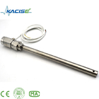
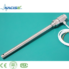
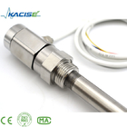
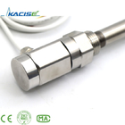
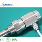
Capacitive intelligent liquid level sensor is a liquid level (material level) transmitter that can be used for liquid, oil, solid, interface and measurement. There are no moving parts, the reliability is greatly improved, it is not affected by water vapor, dust or condensation, and has the advantages of stable and reliable long-term operation, high sensitivity, good linearity, high temperature resistance, high pressure resistance, etc. The intelligent liquid level meter is a two-wire (loop powered) 4~20mADC measurement signal, easy to adjust, wireless transmission, 485 transmission, etc. Can be widely used in petroleum, chemical, metallurgy, electric power, paper, pharmaceutical and other fields.
■Modbus protocol is easy to integrate.
■Simple structure without any movable or elastic components, so it has high reliability and minimal maintenance. Under normal circumstances, it is not necessary to carry out routine large, medium and small maintenance.
■A variety of signal outputs are convenient for different system configurations.
■Suitable for level measurement of high temperature and high pressure containers, and the measured value is not affected by the temperature, specific gravity of the liquid to be measured, and the shape and pressure of the container.
■It is especially suitable for the measurement of strong corrosive liquids such as acid and alkali.
■Perfect overcurrent, overvoltage and power supply polarity protection.
■Wireless level sensor has wireless remote transmission function.
■Can measure any medium.
●Detection range: 0.1~3m
●Capacitance measurement range: 10PF~500PF
●Accuracy: 0.1 class, 0.2 class, 0.5 class, 1 class
●Pressure range: -0.1MPa~32MPa
●Probe temperature resistance: -50~250℃
●Ambient temperature: -40~85℃
●Storage temperature: -55℃~+125℃
●Output signal: 4~20mA, 485 communication, etc.
●The communication distance of wireless output level sensor is less than 200 meters, and the power supply voltage is 3.3-36V (optional battery power supply)
●Power supply voltage: 5~36V DC
●Level sensor material: 316 stainless steel, 1Gr18Ni19Ti or PTFE
●Long-term stability: ≤0.1%FS/year,
●Temperature drift: ≤0.01%FS/ ℃ (within the range of 0~70 ℃)
●Explosion-proof grade: ExibIICT6
●Protection level: IP67
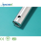
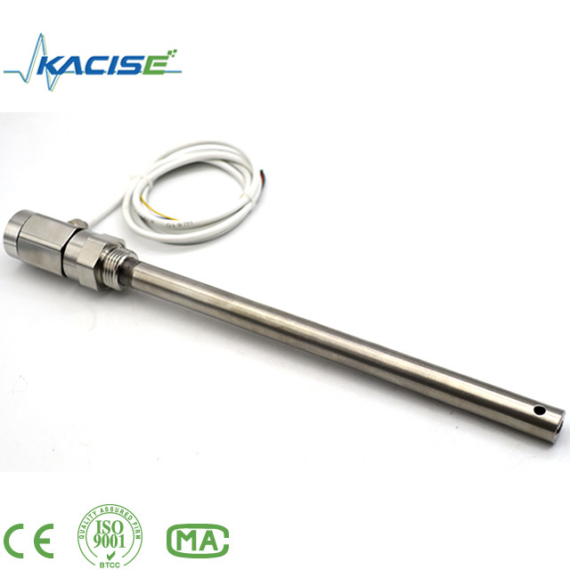
Capacitive liquid level sensors have different structures due to different application occasions and parameters, but in general, its main structure can be roughly divided into two parts, namely the sensor part and the transmitter part. as the picture shows:
A in the picture shows the sensor, which directly probes into the container equipment or measures
in the measured medium of the meter tube
B and C in the figure are the gas phase and liquid phase connection flanges of the liquid level measurement and control instrument, which are used for the connection of the equipment flanges, and the liquid and pressure in the equipment are drawn to the measuring cylinder.
D in the figure shows the measuring cylinder of the liquid level measurement and control instrument, which can form a capacitance with the sensor electrode.
E shown in the figure is the sewage flange, which can regularly discharge the dirt in the liquid level measurement and control instrument to the outside, keep the inside of the measuring tube of the liquid level measurement and control instrument clean, and prevent the sensor from adhering to the dirt.
F shown in the figure is the transmitter, which is a conversion device from capacitance to standard current signal, and is the central part of the entire liquid level measurement and control instrument. Its main function is to receive the capacitance change increment caused by the liquid level change sent by the sensor, and then After conversion, it outputs 4-20mADC standard current signal. This transmitter adopts military integrated devices, with low power consumption, high temperature resistance, strong reliability, and meets the requirements of intrinsic safety.
Note: There is a sealing part between the transmitter and the measuring tube, which is composed of several seals, which can ensure that the measured medium is in contact with the sensor but will not leak out, causing harm. This section is an important sealing part, please do not disassemble it without the consent of the manufacturer to avoid accidents.
5 Display
![]()
KSLV606 (display model) has two ways of wiring: one is RS485, the other is 4-20mA.
![]()
![]()
Isolated 4-20mA output
![]()
Non-isolated 4-20mA 2-wire output
Figure 6.1
After installation, when using it for the first time, make sure to open the gas phase valve first, and then open the liquid phase valve to ensure that the liquid level will not fluctuate violently, causing measurement errors.
In addition, it should be ensured that the connecting cable joints are in good contact and anti-corrosion. In long-term use, pay attention to regular sewage discharge, so as to avoid the accumulation of dirt and affect the performance of the instrument. Taking common copper liquid, C-carbon liquid, Baohe hot water tower, sewage pool and other dirty media as an example, it should be guaranteed to discharge 1 to 2 times a week, while the cleaner medium should be discharged 1 to 2 times a month.
The transmitter housing should be tightly wrapped to prevent water, corrosive medium or gas from entering, and it is forbidden to collide with external force and dismantle it by non-professionals.
There are three common wiring methods for transmitters: as shown in (a) (b) (c)
![]()
(a)
![]()
(b)
![]()
(c)ammeter
Figure 6.2
As shown in the figure above, there are three wiring methods for the transmitter of the liquid level measurement and control instrument. Figure (a) shows the wiring diagram of the transmitter directly and the digital display meter. Figure (b) shows the wiring diagram of the transmitter and the DCS control system. The control system supplies 24V and is connected to the transmitter. Figure (c) shows the connection diagram of the transmitter powered by the safety barrier. Users can refer to the above three wiring methods during installation.
1) Gas phase and liquid phase installation
![]()
Figure 7.1
Since the products are only different in appearance design and material, but both belong to the external liquid level measurement and control instrument, the installation methods of the two are basically the same, which will be explained together here. In general, the installation is extremely simple and fast, just connect the gas-liquid phase connection flange on the liquid level measurement and control instrument with the gas-liquid phase flange on the equipment, add a gasket in the middle, and fix it with bolts. (Note: The connecting flange of the liquid level monitoring and control instrument has been welded according to the size agreed by the two parties, and does not need to be reconfigured. The user should configure the valve and pipeline by himself) as shown in the figure 7.1.
Note: Before installation, be sure to clean the inner hole of the outlet pipe on the equipment to ensure that the outlet pipe of the equipment is unobstructed and the sealing surface of the flange is intact. At the same time, a valve can be added between the flange of the liquid level measurement and control instrument and the flange of the equipment to facilitate the disassembly and assembly of the instrument during maintenance or replacement.
1) Installation of boiler type capacitive liquid level meter
![]()
Figure 7.2
Capacitance level gauge is a product specially used for large, medium and small boiler air bag and other types of high temperature liquid level measurement.
It adopts special materials and radio frequency technology, so that the whole machine can run stably for a long time in a high temperature environment. Because it is specially used in high temperature environment, the structure and installation method of liquid level measurement and control instrument are different from other products.
First of all, it is different from other products in that its transmitter is located under the sensor, there is a sealed and heat-dissipating section from the measuring cylinder to the transmitter, and then downward is a 90-degree curved arm to lead the transmitter to the sensor side, which ensures that the transmitter is protected from high temperatures near the gas port. On the other hand, when the high temperature medium transfers heat downward to the transmitter, it first passes through a special heat dissipation section, which will greatly reduce its heat. Leading the transmitter to the lower side of the sensor is mainly to prevent the leakage of the sealing section of the sensor and prevent the medium from spreading down to the transmitter part along the outer wall of the measuring cylinder, causing short circuit or corrosion.
To sum up, the structure of this level meter has obvious advantages, which is why it can run stably for a long time in a high temperature environment. For installation, it should be noted that the transmitter is below, and the distance from the sewage pipe is relatively close, so it cannot be installed in reverse. The installation is as shown in the figure 7.2:
Although the analog adjustment has been made before the product leaves the factory, in order to allow the user to further experience the performance of our product before use, it is recommended that the user perform a simple verification. You can remove the whole set of instruments for calibration. (But do not disassemble the parts of our products)
The calibration of the external liquid level measurement and control instrument is shown in the figure 8.1:
![]()
Figure 8.1
The verification steps are as follows:
1) Prepare a transparent water pipe, mark it with a scale or fix it with a ruler, so that the actual liquid level can be observed and calibrated during calibration. In addition, prepare an ammeter (DC) with a precision of more than three digits, several rubber stoppers, and enough test medium (which can be replaced by water).
2) Connect one end of the transparent water pipe to the liquid phase port of the liquid level measurement and control instrument, block the sewage outlet, and keep the gas phase port unobstructed. And connect the ammeter in series as shown in Figure 6.2), and then turn on the power after confirming that the wiring is correct.
3) Add the medium from the upper end of the transparent tube, the medium flows through the liquid phase tube into the liquid level measurement and control instrument, and the liquid level is added to several points with different heights, because at this time the liquid level in the transparent tube is measured with the liquid level measurement and control instrument. The liquid level in the meter cylinder is exactly in line. At this time, read the value of the ammeter, and then compare the height ratio corresponding to the output standard 4-20mA signal with the collected current value to check the accuracy of the level meter (Note: In order to It is easy to calculate. Generally, several points are taken at 0%, 25%, 50%, 75% and 100% respectively, and the corresponding currents are 4mA, 8mA, 12mA, 16mA and 20mA respectively. The range should correspond to the center of liquid phase and gas phase respectively).
1. During use, if the digital display indicates zero, use the 0-200mA range of the DC ammeter, and when the measured current is also 0, the possible faults are:
a. Is the 24V power supply normal?
b. The transmitter may be short-circuited
c. The transmitter has quality problems;
If the current measured by the DC ammeter is less than 4mA, the possible faults:
a. The actual liquid level is below the liquid phase port
b. The current adjustment value of the transmitter is too low
c. The transmitter has quality problems; if the measured current is consistent with the actual liquid level, there is a problem with the digital display;
Possible failures if the current exceeds 25mA:
a. There is a short circuit in the transmitter circuit
b. The current adjustment value is too high.
2. When the digital display is full, use the 0-200mA range of the DC ammeter. When the measured current is 20mA, there may be a fault:
a. The current adjustment is too high
b. There is a short circuit in the transmitter
c. The actual liquid level is full;
If the measured current is less than 20mA, the digital display is faulty.
3. The digital display jumps violently. Using the 0-200mA range of the DC ammeter, the measured current fluctuates too much and may malfunction:
a. Actual liquid level fluctuation
b, poor line contact
c. The transmitter has quality problems; if the measured current is stable, the display meter may be faulty
4. There is no change in the digital display. Use the 0-200mA range of the DC ammeter. When the measured current changes normally, it may indicate that the instrument is faulty; if the measured current does not change, there may be a fault:
a. Transmitter failure
b. The gas-liquid phase pipe is blocked
c. There is an open circuit between the sensor and the transmitter and must be reconnected
5. The digital display changes slowly than the actual liquid level. When using the ammeter 0-200mA, the measured current changes slowly, and there may be a fault:
a. The inner pole of the sensor sticks to impurities, use 25% hydrochloric acid (sulfuric acid) to soak the pole
b. The gas phase pipe is half blocked, please open the valve, and test it, clear it.
6. When the digital display is high or low, adjust the range or zero knob in the transmitter to adjust.
Note: To measure whether there is 24V power supply in the circuit, please use the positive and negative test leads of the voltmeter to connect the positive and negative of the 24V power line before measuring.
Handling of the existence of short circuit: please check the external circuit and the transmitter circuit and eliminate it.
1. All supplied products are provided with product certificate and instruction manual, including product number, technical parameters, wiring diagram, date of manufacture, etc. Please check carefully to avoid wrong use.
2. During installation, check whether the on-site interface is consistent with the product interface according to the connection method of the product.
3. The wiring should be wired in strict accordance with the requirements of our company's instructions for use.
4. This product is a precise energy-transducing instrument, and it is forbidden to disassemble, collide, drop, and beat with force.
5. If any abnormality is found during use, you should turn off the power, stop using it, check it, or contact the technical department of our company directly.
6. The original packaging should be restored during transportation and storage, and stored in a cool, dry and ventilated warehouse.
7. Be careful not to damage the sensor during installation and use.
8. Effective lightning protection measures should be taken at the installation site.
9. The casing of any transmitter in this series must be grounded reliably, and the grounding resistance should be less than 4Ω.
10. When using 485 communication for system configuration, the transmitter must be equipped with a safety barrier or isolator.
11. The safety barrier should obtain an explosion-proof certificate, and its installation should be carried out according to the requirements of its manual.
12. When the transmitter is used in the "0" area, the power transformer supplying power to the safety barrier must meet the requirements of Article 8.1 of GB3836.4-2010.
Product Selection Table
| KSLV | Selection table for intelligent capacitive fluid level gauge | |||||||
| Product type | ||||||||
| 605 | No display model | |||||||
| 606 | No display model | |||||||
| Output Signal | ||||||||
| 4-20mA |
4~20mA signal output, LED display |
|||||||
| RS485 | RS485 output | |||||||
|
Code |
Measuring range |
|||||||
| L500 | 500mm | |||||||
| L800 | 800mm | |||||||
| L1000 | 1000mm | |||||||
| Lxxx | Special requirements please fill in the bracket | |||||||
|
Measuring media |
Identify the type of medium being measured, such as water, diesel... |
|||||||
|
Water |
The measured medium is water |
|||||||
|
other |
Please note clearly if there are other requirements |
|||||||
|
NA |
||||||||
| KSLV | 605 | 4-20mA | L800 |
water |
NA |
|||
Contact Person: Ms. Evelyn Wang
Tel: +86 17719566736
Fax: 86--17719566736
Address: i City, No11, TangYan South road, Yanta District, Xi'an,Shaanxi,China.
Factory Address:i City, No11, TangYan South road, Yanta District, Xi'an,Shaanxi,China.