
 |
| Place of Origin: | CHINA |
| Brand Name: | kacise |
| Certification: | CE |
| Model Number: | KFDO601 |
| Minimum Order Quantity: | 0-100 |
|---|---|
| Price: | $0-$2000 |
| Packaging Details: | Common package or custom package |
| Delivery Time: | 3-10days |
| Payment Terms: | L/C, D/A, D/P, T/T, Western Union, MoneyGram |
| Supply Ability: | 100 |
| Measuring Principle: | Fluorescence Method | Range Ability: | 0~20mg/L (0 ≤ 200% Saturation) |
|---|---|---|---|
| Resolution Ratio: | 0.01mg/L,0.1℃ | Precision: | ±2%F.S.,±0.5℃ |
| Temperature Compensation: | Automatic Temperature Compensation(Pt1000) | Output Mode: | RS-485 Bus, Modbus-RTU Protocol |
| High Light: | Rs-485 interface dissolved oxygen sensor,anti interference dissolved oxygen sensor,20mg/L optical dissolved oxygen sensor |
||
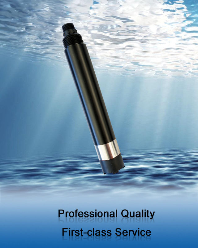
KFDO601 Online Fluorescence Dissolved Oxygen No Electrolyte Is Required And Will Not Be Polarized No Oxygen Consumption
1.Operational Principle
KFDO601 integrated on-line fluorescence dissolved oxygen sensor is designed and fabricated based on the quenching principle of excited fluorescence by specific substances in physics. When the excitation light is shone on the fluorescent material on the surface of the fluorescent film head, the fluorescent material is excited and emits fluorescence. The quenching time of fluorescence is affected by the concentration of oxygen molecules on the surface of the fluorescent film head.By detecting the phase difference between fluorescence and excitation light and comparing with the internal calibration curve, the concentration of oxygen molecules can be calculated, and the final value can be output after temperature and salinity compensation.
![]()
2.Feature
| Model | KFDO601 |
| Measuring principle | Fluorescence method |
| Range ability | 0~20mg/L (0 ≤ 200% saturation) |
| Resolution ratio | 0.01mg/L,0.1℃ |
| Precision | ±2%F.S.,±0.5℃ |
| Temperature compensation | Automatic temperature compensation(Pt1000) |
| Output mode | RS-485 bus, Modbus-RTU protocol |
| Working conditions | 0~45℃,<0.2MPa |
| Storage temperature | -5~65℃ |
| Installation mode | Immersion mounting |
| Cable length | 5 meters, other lengths customizable |
| Power dissipation | <0.3W@12V |
| Source | 12~24VDC ±10% |
| levels of protection | IP68 |
| Calibration | Two-point calibration |
| Fluorescent cap life | Guaranteed use for one year (under normal use) |
| Sensor shell material | POM and 316L stainless steel |
![]()
Note:The sensor connector is m16-5 core waterproof connector male.
![]()
The sensor shall be installed fixedly below the liquid level. The installation and use shall avoid collision or scraping against the surface of the fluorescent film head. The fluorescent film head part shall avoid being attached by the bottom sediment.Remove the rubber cover when use.
Check wiring sequence carefully before power on to avoid unnecessary losses caused by wiring errors.
Wiring instructions: Considering that the cables have been immersed in water (including seawater) or exposed to air for a long time, all wiring positions are required to be waterproof, and the cables should have certain corrosion resistance.
6.1.1 Maintenance Schedule
Different from the dissolved oxygen probe technology of electrochemical principle, the fluorescence dissolved oxygen probe does not consume oxygen and does not need to be cleaned frequently (except when it is used in viscous liquid).
| Maintenance Task | Recommended Maintenance Frequency |
| Cleaning sensor | Wash every 30 days |
| Check for damage to sensors and fluorescent caps | Check every 30 days |
| Replace the fluorescent cap | Replace it once a year |
|
Calibrate sensors (if required by the competent authority))
|
According to the maintenance schedule required by the competent department |
Note: The maintenance frequency in the above table is only recommended, and the maintenance personnel shall clean the sensor according to the actual use of the sensor; however, the replacement frequency of the fluorescent cap is recommended once a year.
6.1.2 Maintenance Method
a) Sensor outer surface: clean the outer surface of the sensor with tap water, if there is still debris residue, wipe with wet soft cloth, for some stubborn dirt, you can add some household washing liquid to tap water to clean.
b) Surface of fluorescent film head: If there is dirt on the surface of fluorescent film head, please rinse with clean water or wipe gently with a soft cloth.Pay attention to the intensity of cleaning to avoid causing scratches in the measuring area and affecting the measurement accuracy.
c) Inside the fluorescent film head: it is generally unnecessary to clean. If water vapor or dust enters into the fluorescent film head, the cleaning steps are as follows:
d) Check the cables of the sensor: there should be no damage to the skin and root of the cables;Terminals should not be submerged in water;When the sensor is normally installed, the cable should not be tensioned, otherwise the internal wire of the cable will easily break and the sensor cannot work normally.
e) Check whether the casing of the sensor is damaged by corrosion or other causes.
f) Daily storage of fluorescent film head: When not in use, a rubber protective cover with a wet sponge should be covered to keep the surface of the measuring area of fluorescent film head wet.If the surface of the measuring area of the sensor fluorescent film head is chronically dry, measurement error or data instability will occur, and it shall be soaked in water for 48 hours before use.
| Wrong | Probable Cause | Solution |
| The operating interface cannot connect or does not display the measurement results | Error connecting controller to cable | Reconnect the controller and cable |
| Cable failure | Please contact us. | |
| The fluorescent cap is not tightened or damaged | Refit and tighten the fluorescent cap or replace the fluorescent cap. | |
| The measured value is too high, too low, or the numerical value remains unstable. | The outer surface of the fluorescent cap is attached to the outer object | Clean the outer surface of the fluorescent film head and agitate the film head during measurement. |
| The fluorescent cap was damaged | Replace the fluorescent cap | |
|
The fluorescent cap has exceeded its service life
|
||
| Temperature measurements change slowly. | The temperature measuring area (stainless steel housing) is attached to the exterior | Gently brush the attachment with a soft brush |
a) Zero Calibration
Weighing 5 g of sodium sulfite by a balance, adding 95mL of water into a 250-mL measuring cylinder, pouring the water into a beaker, adding the sodium sulfite which has been weighed, stirring with a glass rod, dissolving, and obtaining a solution of 5% sodium sulfite, putting the sensor in a solution, And the zero point calibration is carried out after the three-minute numerical stability is stable. Refer to the Appendix to the instructions
b) Slope Calibration
The sensor probe is placed in air saturated water and the slope is calibrated after 3 minutes of numerical stability. The instructions refer to the appendix.
c) Preparation of Air Saturated Water: add 2% 3 volume fresh distilled water to the constant temperature water bath to float the porous plastic sheet on the water surface (see figure below). At the same time, the bubbler (air pump) is used to aerate the water continuously for more than 1 hour, stop aeration, and get air saturated water after 20 minutes or so. Put the sensor into the water and calibrate the
slope after the numerical value is stable.
![]()
Note: as an option, slope calibration can also be performed in water-saturated air. Put the sensor in a calibration bottle with a small amount of water (the probe is higher than the water surface 2-3mm) to ensure that the sensor film cap remains wet but has no water droplets, and the calibration slope is calibrated after 3 minutes of numerical stability.
This product includes:
The company provides after-sales service for this machine within one year from the date of sale, but does not include the damage caused by improper use. If you need to repair or adjust, please send it back, but the freight must be borne by yourself, and it is necessary to make sure that the packing is good to avoid damage in transit. We will repair the damage of the instrument free of charge.
Website www.kacise.com
Phone +86-17719566736
Email sales@kacise.com
Location Tangyan South Road, High-tech Zone, Xi'an City, Shaanxi Province, China
![]()
Contact Person: Ms. Evelyn Wang
Tel: +86 17719566736
Fax: 86--17719566736
Address: i City, No11, TangYan South road, Yanta District, Xi'an,Shaanxi,China.
Factory Address:i City, No11, TangYan South road, Yanta District, Xi'an,Shaanxi,China.


