Mass Flow Meters Installation and Operation Manual
1.Introduction
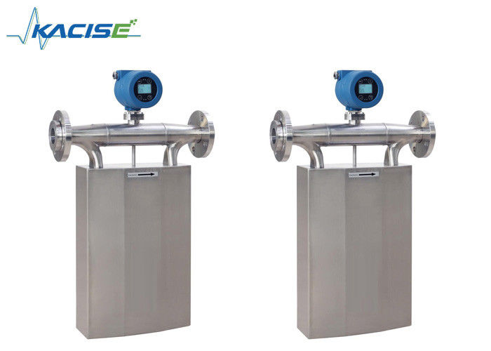
Kacise Mass Flow Meters patented and developed by our company are the leading meters for precision flow measurement. And with good reason, the meters offer the most accurate measurement available for virtually any process fluid, while exhibiting exceptionally low pressure drop. The meters offer direct mass flow, volume flow, density, and temperature measurement of liquids and slurries — without the need for additional equipment, manual calculations, or estimations.
The meters are designed for unsurpassed performance in even the harshest operating environments. They have no moving parts, and any special mounting or flow conditioning requirements. Every meter is available with stainless steel wetted parts and a wide variety of process connections to meet your every need.
The meters carry hazardous area approval for P. R. China.
2.product feature
The instrument is based on the Coriolis Force principle and enables direct and accurate measurement of mass flow without any conversion, correction or modification of pressure, temperature, viscosity, or density. (Kg / h, t / h or g / s) are directly displayed on the electronic unit panel and output on the back of the electronic unit. 0-10kHz, 4- 20mA and RS485 communication protocol. The flowmeter has no moving parts, wide range, accuracy (± 0.2%), high pressure, wide temperature range, can be used to measure high viscosity (10000CP) and non-Newtonian fluid flow. The characteristics of the instrument in the oil field, refinery, chemical, building materials, food, medicine, leather, paper, paint, dyes, nuclear energy, metallurgy, aerospace and other sectors are widely used. Flow sensor measurement tube 316L stainless steel or Kazakhstan C alloy material, the sensor components are not in contact with the medium, good corrosion resistance.
Instrument installation using quick and easy, stable and reliable operation, is currently the most flow characteristics of many instruments, the most popular new mass flowmeter. The instrument according to intrinsically safe explosion-proof design and manufacture of national standards, explosion-proof mark for EX d ib IICT5Gb.
3.Typical application

4. Instrumentation dimensions
Instrumentation Dimensional Drawings
Dimensions of large - scale instrument
Unit:mm
|
Model
|
Weld Neck Flanges-ANSI B16.5 |
A
|
B
|
C
|
E
|
F
|
W
|
G
|
K
|
d
|
D
|
| DN |
LB |
| KMF-1-6c |
100 |
150 |
670 |
510 |
740 |
858 |
1092 |
260 |
19.1 |
190.5 |
157.2 |
228.6 |
| KMF-1-6CD |
125 |
150 |
670 |
510 |
740 |
858 |
1092 |
260 |
22.4 |
215.9 |
185.7 |
254 |
| KMF-1-6D |
150 |
150 |
860 |
670 |
950 |
1130 |
1370 |
280 |
22.4 |
241.3 |
215.9 |
279.4 |
Dimension of medium - sized instrument
| Model |
Dimension of medium - sized instrument |
A |
B |
C |
E |
F |
W |
G |
K |
d |
D |
| DN |
PN(MPa) |
| KMF-1-3A |
10 |
4.0 |
280 |
210 |
235 |
285 |
485 |
80 |
14 |
60 |
41 |
90 |
| Model |
langeGB-/T 9112-9124- 2000 |
A |
B |
C |
E |
F |
W |
G |
K |
d |
D |
| DN |
lb |
| KMF-1-3B |
15 |
300 |
280 |
210 |
275 |
325 |
525 |
80 |
15.7 |
66.55 |
35 |
95.2 |
| KMF-1-4 |
20 |
300 |
290 |
230 |
325 |
375 |
575 |
90 |
19 |
82.5 |
42.9 |
117.3 |
| KMF-1-5A |
25 |
300 |
410 |
300 |
440 |
500 |
696 |
120 |
19 |
88.9 |
50.8 |
123.9 |
| KMF-1-5B |
40 |
300 |
520 |
360 |
480 |
585 |
790 |
130 |
22.3 |
114.3 |
73.15 |
155.4 |
| KMF-1-6A |
50 |
150 |
550 |
370 |
548 |
670 |
875 |
153 |
19.1 |
120.7 |
91.9 |
152.4 |
| KMF-1-6AB |
65 |
150 |
560 |
440 |
600 |
715 |
936 |
200 |
19.1 |
139.7 |
104.6 |
177.8 |
| KMF-1-6B |
80 |
150 |
600 |
470 |
650 |
767 |
988 |
220 |
19.1 |
152.4 |
127 |
190.5 |
Miniature instrument appearance dimensions
Unit: mm
| Model |
Take over the
outside diameter
|
PN(MPa) |
A |
B |
C |
E |
F |
W |
G |
| KMF-1-1-A |
6 |
25 |
160 |
165 |
180 |
140 |
150 |
53 |
7 |
| KMF-1-1-B |
8 |
25 |
160 |
165 |
180 |
140 |
150 |
53 |
7 |
| KMF-1-2-A |
8 |
25 |
175 |
208 |
245 |
185 |
188 |
53 |
7 |
Micro - bending instrument appearance size
Unit:mm
| Model |
DN |
L |
H |
W |
H1 |
| KMF-1-V-10 |
10 |
550 |
160 |
68 |
360 |
| KMF-1-V-15 |
15 |
580 |
170 |
68 |
370 |
| KMF-1-V-20 |
20 |
640 |
200 |
68 |
400 |
| KMF-1-V-25 |
25 |
780 |
320 |
100 |
520 |
| KMF-1-V-50 |
50 |
900 |
230 |
108 |
460 |
| KMF-1-V-80 |
80 |
995 |
260 |
140 |
515 |
| KMF-1-V-100 |
100 |
1300 |
350 |
150 |
605 |
| KMF-1-V-150 |
150 |
1750 |
490 |
262 |
805 |
| KMF-1-V-250 |
250 |
1920 |
510 |
262 |
825 |
Transmitter dimensions size
Unit:mm
| |
L |
L1 |
L2 |
L4 |
L5 |
L6 |
L7 |
L8 |
L9 |
H4 |
| Transmitter |
156 |
125 |
118 |
130 |
54 |
102 |
180 |
45.4 |
85 |
32 |
Signal output and Power Supply
5. Installation method
Horizontal installation-Normal
Suitable for liquid measurement conditions ,To ensure that the gas may exist in the gas discharge
Horizontal installation-reverse
Suitable for gas measurement conditions,To ensure that the fluid may be condensate discharge
Flag installation with bypass
For liquids and high viscosity,High Temperature liquid,And requirefrequent emptying of the fluid from the pipeline
Flag installation simple
Be suitable for overflow conditions,But the Throttle device at the outlet of the flow meter is very important,If there is no throttle device may produce siphon effect,Affect the measurement of the fluid
6.Instrument Selection
| Code: KMF-1- Product Flow meter selection guide |
| |
Code |
DN/Measuring range |
| |
1A |
Diameter:3mm, 0-40kg/h |
| |
1B |
diameter:6mm, 0-100kg/h |
| |
2A |
diameter:8mm, 0-200kg/h |
| |
3A |
diameter:10mm, 0-5000kg/h |
| |
3B |
diameter:15mm, 0-1000kg/h |
| |
4 |
diameter:20mm, 0-3000kg/h |
| |
5A |
diameter:25mm, 0-10th/h |
| |
5B |
diameter:40mm, 0-20th/h |
| |
6A |
diameter:50mm, 0-30th/h |
| |
6AB |
diameter:65mm, 0-50th/h |
| |
6B |
diameter:80mm, 0-100th/h |
| |
6C |
diameter:100mm, 0-150th/h |
| |
6CD |
diameter:125mm, 0-200th/h |
| |
6D |
diameter:150mm, 0-500th/h |
| |
6E |
diameter:200mm, 0-800th/h |
| |
6F |
diameter:250mm, 0-1000th/h |
| |
|
Code Transmitter output |
| |
|
A |
4-20mA(Instantaneous flow or density is optional); 0-10KHz(Instantaneous flow pulse signal); RS485 Modbus RTU; HART |
| |
|
|
Code Transmitter housing |
| |
|
|
B |
Die-cast aluminum alloy shell Wiring hole dimensions:M20*1.5 |
| |
|
|
|
Code Pressure rating |
| |
|
|
|
16 |
1.6MPa |
| |
|
|
|
40 |
4.0MPa |
| |
|
|
|
xx |
Special customization:using this letter to ask for the customization, please inform the pressure rating |
| |
|
|
|
|
Code Temperature rating |
| |
|
|
|
|
A |
-50~150℃ |
| |
|
|
|
|
B |
-50~250℃ |
| |
|
|
|
|
C |
-50~350℃ |
| |
|
|
|
|
D |
-200~150℃ |
| |
|
|
|
|
|
Code Accuracy class |
| |
|
|
|
|
|
N |
0.20% |
| |
|
|
|
|
|
M |
0.15% |
| |
|
|
|
|
|
H |
0.10% |
| |
|
|
|
|
|
|
Code Pressure link |
| |
|
|
|
|
|
|
F |
Standard Flanges GB/T 9123.1-2000 ANSI Weld Neck Flanges-ANSI B16.5 |
| |
|
|
|
|
|
|
W |
Health type |
| |
|
|
|
|
|
|
L |
Welding thread |
| |
|
|
|
|
|
|
T |
Customization |
| |
|
|
|
|
|
|
|
Code Inspection certificate |
| |
|
|
|
|
|
|
|
F |
Factory standard:factory test certificate |
| |
|
|
|
|
|
|
|
I |
GB:third-party verification certificate |
| |
|
|
|
|
|
|
|
|
Code Material |
| |
|
|
|
|
|
|
|
|
A |
Measuring tube:316L |
| |
|
|
|
|
|
|
|
|
C |
Measuring tube:Hastelloy |
| |
|
|
|
|
|
|
|
|
F |
Measuring tube:inner wall spray PTFE(for large diameter) |
| |
|
|
|
|
|
|
|
|
T |
Special customization:using this letter to ask for the customization, please inform the pressure rating |
| |
|
|
|
|
|
|
|
|
|
Code Transmitter |
| |
|
|
|
|
|
|
|
|
|
A |
Integrated type |
| |
|
|
|
|
|
|
|
|
|
B(XX) |
Split type(cable length), with bracket |
| |
|
|
|
|
|
|
|
|
|
|
Code Explosion-proof mark |
| |
|
|
|
|
|
|
|
|
|
|
A |
Exd II CT5 Gb |
| KMF-1- |
3b(0~800kg/h) |
A |
B |
40 |
A |
N |
F |
F |
A |
B(10) |
A |
Typical Orders information |

 Your message must be between 20-3,000 characters!
 english
 français
 Deutsch
 Italiano
 Русский
 Español
 português
 Nederlandse
 ελληνικά
 日本語
日本語
 한국
한국
 العربية
 हिन्दी
 Türkçe
 indonesia
 tiếng Việt
 ไทย
ไทย
 বাংলা
বাংলা
 فارسی
فارسی
 polski