logo
Home > products > Ultrasonic Transducer Sensor >
Oem Ultrasonic Proximity Distance Meter Sensor KUS3000 Series with protection class IP66

Oem Ultrasonic Proximity Distance Meter Sensor KUS3000 Series with protection class IP66

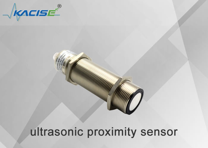
Ultrasonic Proximity Distance Meter Sensor

KUS3000 Series Ultrasonic Transducer Sensor

Ultrasonic Distance Meter Sensor

Place of Origin:

China

Brand Name:

Kacise

Certification:

CE

Model Number:

KUS3000

Contact Us
Request A Quote
Product Details
Range:
1m~12m
Output:
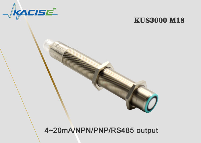
4~20mA/NPN/PNP/RS485
Protection Class:
IP66
Power Supply:
13-30V
Material:
Nickel Plated Copper
Temperature:
-25~70℃
Accuracy:
≤1 %
Highlight:

Ultrasonic Proximity Distance Meter Sensor

,

KUS3000 Series Ultrasonic Transducer Sensor

,

Ultrasonic Distance Meter Sensor

Payment & Shipping Terms
Minimum Order Quantity
1
Price
Negotiable
Packaging Details
15*20*15cm,0.3kg
Delivery Time
5-8 work days
Payment Terms
L/C, D/A, D/P, T/T, Western Union, MoneyGram
Supply Ability
100+
Product Description

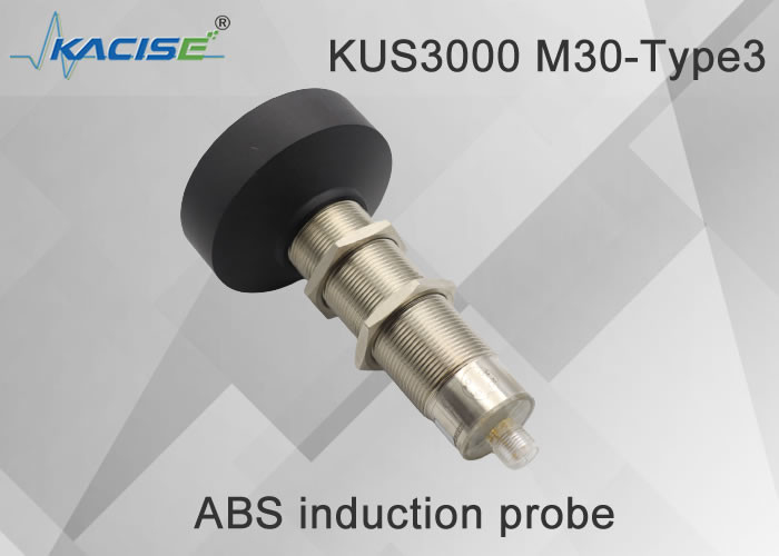
KUS3000 M30-Type3​ Ultrasonic Level Meter

Oem Ultrasonic Proximity Distance Meter Sensor KUS3000 Series with protection class IP66 0

  • Compact and durable
  • IoT-specific models
  • High resolution and small dead zone


1. Dimensional structure


The unit is mm.

Oem Ultrasonic Proximity Distance Meter Sensor KUS3000 Series with protection class IP66 1


2. Electrical interface


Oem Ultrasonic Proximity Distance Meter Sensor KUS3000 Series with protection class IP66 2

Note: This product has two cable specifications, and the cable wiring instructions of the two specifications are as follows:

Type A cable Type B cable
Pin1 Brown Pin1 Yellow
Pin2 White Pin2 Black
Pin3 Blue Pin3 Red
Pin4 Black Pin4 Green

The default cable mix is based on the specifications received by the customer


3. Technical parameter


Model KUS3000 M18 KUS3000 M30-Type1, M30-Type2, M30-Type3
Measuring range 0.15~1m/0.2~2m/0.3~4m/0.4~6m/0.6~12m
Supply voltage 13 ... 30 VDC, special wide voltage requirements can be customized
Output signal 1.4-20mA/NPN/PNP/TTL;    2. RS485 Modbus.
No-load current I0 ≤ 45 mA
Overload current Ie 200 mA , reverse polarity protection, short circuit protection
Power consumption I0 ≤ 15 mA, sleep state ≤ 1mA, serial port wake-up
Repeatability ≤1%
Temperature compensation range -40…85°C
Working environment temperature -25...70℃ (248...343K)
Storage temperature -40...85°C (233...358K)
Switching frequency f ≤ 13 Hz high frequency can be customized
Protection level IP66, others can be customized
Shell material nickel-plated copper, others can be customized
Connector V1 connector (M12×1), 4-Pin
Supply voltage 3.3-12 DC, ripple 10%SS

Indicator light

Blue led light The blue light flashes to indicate that calibration can be performed. Blue and other constants indicate that the power supply of the sensor is normal. The blue light will flash within 5 minutes after the power is turned on, indicating that the user can perform output adjustment and calibration. After 5 minutes, the blue light is always on to indicate that the sensor cannot be receiving Calibration command. .
Tellow led light It is used to indicate whether the measured object is detected. During the calibration stage, the yellow light flashes to indicate that the current calibration state is locked, and it can be switched to the next calibration state.
Red LED light

In normal working state, the red light is not on, and the red light is on to indicate that there is a fault.

During the calibration process, the flashing red light indicates that the sensor locks the current echo loss or infinity state, and the user can switch to the next calibration state.


Note: When the M18 product and M30 product have 4-20mA analog output, the meter connection method is different from that of the 550,600 product. Since the output terminal of the M18 and M30 products is powered by VDD, as shown in Figure 1, the meter should be connected to the power supply port. Between the output terminal and the output terminal, the connection instruction diagram is shown in Figure 2:

Oem Ultrasonic Proximity Distance Meter Sensor KUS3000 Series with protection class IP66 3

Figure 1 Output power supply circuit diagram

Oem Ultrasonic Proximity Distance Meter Sensor KUS3000 Series with protection class IP66 4

Figure 2 Schematic diagram of connection method


4. Order information


KUS Types of output range describe
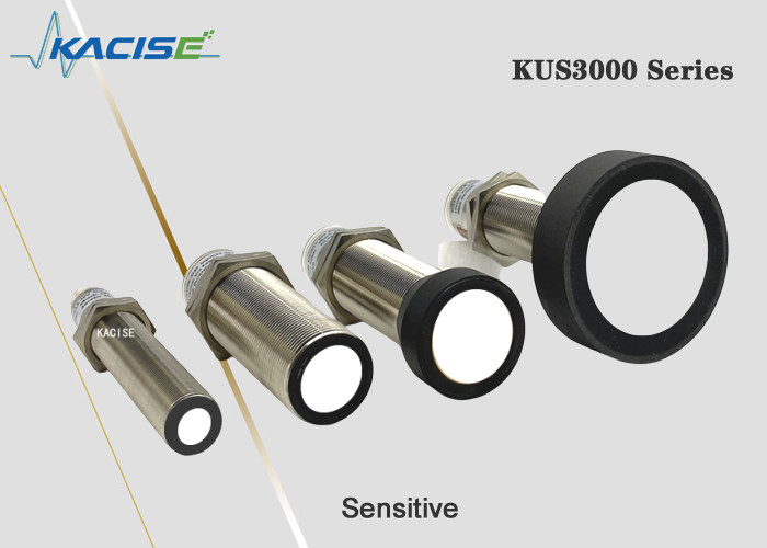
  M18 M18 housing, maximum measuring range is 1 meter
M30-Type1 M30 maximum measuring range is 2 meter
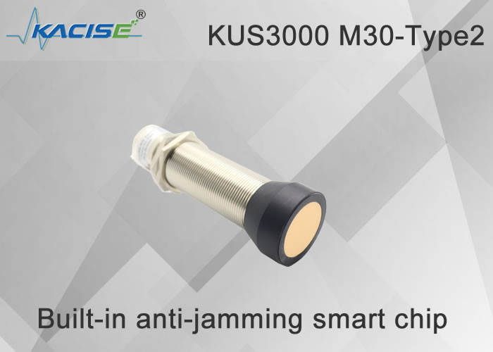
M30-Type2 M30 maximum measuring range is 3 meter
M30-Type3 M30 maximum measuring range is 6 meter, 8 meters can be customized
Customized Shell supports user customization
  NPN output as NPN
PNP output as PNP
10Vout The output is analog 0-10V, the power supply requirement is greater than 11V
5Vout The output is analog 0-5V, the power supply requirement is greater than 6V
mAout The output is analog 4-20mA
RS485 The output is RS485 Modbus protocol, please refer to the software interface manual for specific description.
    XXX mm The customer specifies the linear interval or switch interval, which can be set at the factory
KUS M30 RS485 6000mm  


5.Application


Oem Ultrasonic Proximity Distance Meter Sensor KUS3000 Series with protection class IP66 5Oem Ultrasonic Proximity Distance Meter Sensor KUS3000 Series with protection class IP66 6

Send your inquiry directly to us

Privacy Policy China Good Quality Fluid Level Meter Supplier. Copyright © 2018-2025 Xi'an Kacise Optronics Co.,Ltd. . All Rights Reserved.