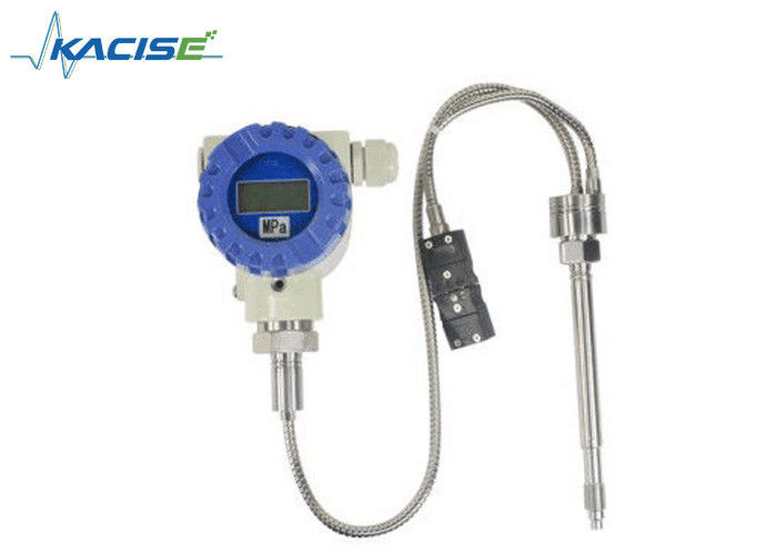
Rigid Stem Sanitary Melt Pressure Transducer Non Toxic Material For Food Process Equipment

Description
GX MPTD-5000 series Melt Pressure Transducer(rigid stem & sanitary)can measure the pressure and temperature in one point, which can be widely used in Medicine & Food process equipment. The model 5000T is with thermocouple. Zero & span can be adjustable; with amplified signal can be connected with PLC. It has the advantages of high precision and reliable, good quality, internal 80% calibration.
Feature
- Simple installation
- High-standard quality
- Stainless steel welding
- 80% internal calibration
- Excellent stability and repeatability
- Adopt environmental and non-toxic material
Application
- Chemical fiber Equipment
- Plastic and Rubber manufacturing equipment
- Medicine & Food process equipment, etc
- Other pressure measure and control
Specification
| Parameter |
| Range |
0…3.5MPa to 0…150MPa |
| Output |
3.33mV/V, 2.00mV/V |
| Accuracy |
±1.0%FS, ±1.5%FS |
| Power supply |
10VDC (6~12) VDC |
| Repeatability |
±0.2%FS |
| Bridge resistance |
350 ohms±10% |
| Overload pressure |
1.5×FSO |
| Internal calibration |
80%±1.0% |
| Insulation Resistance |
200MΩ @ 100Vdc |
| Max. Diaphragm Temp |
200°C |
| Membrane material |
15-5PH coated stainless steel |
| Electric connector |
5PIN, 6PIN |
| Process connector |
1/2”-20UNF, M14×1.5, M18×1.5 (Customer design) |
Dimension
MPTD-5000

MPTD-5000T

Ordering Guide
| Model |
Range(bar) |
Output |
Screw Thread |
Electric connection |
Other requirement |
| MPTD-5000(T) |
--- |
--- |
--- |
--- |
--- |
| Example: MPTD-5000-500Bar-3.33mV/V-M14×1.5-6PIN |
Installation Precautions
Installation
The diaphragm of the sensor is the most easily damaged part, please do not drop the protective cap before installation, and in the installation should pay attention to the protection of the sensor diaphragm. The processing of mounting holes should be processed according to the technical requirements of the installation hole size and size table, to avoid the installation of the hole is not standard caused the scratch the diaphragm of the sensor and impact the sensor normal work.
Dismantle
To ensure that the installation of the hole is not left behind the metal foreign body or plastic, all sensors should be removed from the machine prior to cleaning up the extruder, the sensor can be removed only when the polymer is in a hot molten state, remove and immediately using a soft cloth to wipe the sensor probe diaphragm. Xi'an Kacise Optronics Tech Co., Ltd. can provide the installation hole of the special cleaning tool to clean up the residual material in the hole in order to facilitate the next installation.
Start-up
Ensure adequate heating and melting time before equipment is started, in order to ensure that all the materials in the membrane part of the sensor before the extrusion machinery work is in the melting state.
Location
The probe of the sensor can resist high temperature, But the temperature of the shell must be below 80°C, therefore, in the process of installing and using, the user must pay attention to the installation of the sensor shell part fixed in room temperature environment. The isolation of the shell and the high temperature region is beneficial to improve the measurement precision and the service life of the sensor.
Overload effect
In the process of actual pressure control, preferably within the rated pressure, although the sensor has a certain overload capacity, but the long time overload will affect the sensor's measurement accuracy and service life.
Electrical connection
In the electrical connection, the transmitter's signal output connecting cable must be connected separately through the wiring slot to avoid the interference of the scene.
Right and wrong of mounting hole size schematic diagram
Mounting Hole
| Planar Sealed |
 |
D1 |
M18×15 |
M22×15 |
G3/8” |
G3/4” |
| D2 |
Φ10.2 |
Φ16.1 |
Φ10.2 |
Φ18.3 |
| D3 |
Φ15.5 |
Φ20.1 |
Φ14.5 |
Φ24.2 |
| M |
Φ19 |
Φ23 |
Φ17 |
Φ28 |
| A |
11 |
11 |
9 |
11 |
| B |
13 |
13 |
10 |
14 |
| C |
40 |
25 |
25 |
40 |
| 45° Slope Sealed |
 |
D1 |
M12×1.5 |
M14×1.5 |
1/2-20UNF |
M18×1.5 |
| D2 |
Φ8.1 |
Φ8.1 |
Φ8.1 |
Φ10.2 |
| D3 |
Φ10.8 |
Φ12.5 |
Φ11 |
Φ15.5 |
| D4 |
Φ13 |
Φ15 |
Φ14 |
Φ19 |
| A |
6 |
6 |
6 |
6 |
| B |
9 |
9 |
9 |
11 |
| C |
16 |
16 |
16 |
20 |
Schematic diagram of electrical connection


 Your message must be between 20-3,000 characters!
 Please check your E-mail!
  Your message must be between 20-3,000 characters!
 Please check your E-mail!


