Send Message
Home ProductsFluid Level Meter

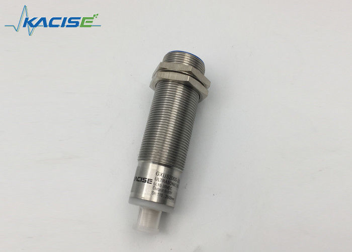
40KHZ Frequency Ultrasonic Distance Sensor 50mm - 1000mm Detection Range

40KHZ Frequency Ultrasonic Distance Sensor 50mm - 1000mm Detection Range

  • 40KHZ Frequency Ultrasonic Distance Sensor 50mm - 1000mm Detection Range
40KHZ Frequency Ultrasonic Distance Sensor 50mm - 1000mm Detection Range
Product Details:
Place of Origin: China (Mainland)
Brand Name: Kacise
Certification: certificate of explosion-proof,
Model Number: M18 KUS1000
Payment & Shipping Terms:
Minimum Order Quantity: 0-100
Packaging Details: each unit has individual box and all boxes are packed in standard packages or customers requests available
Delivery Time: 5-8 work days
Payment Terms: T/T, Western Union, MoneyGram
Supply Ability: 1000 Pieces per Week
Contact Now
Detailed Product Description
Product: Ultrasonic Distance Sensor Detection Range: 50mm~1000mm
Transducer Frequency: 40KHZ Operating Voltage: 24VDC
Limit Working Voltage: 3.6VDC~30VDC IP Grade: IP67
High Light:

ultrasonic level transmitter

,

ultrasonic liquid level sensor

KUS series ultrasonic transmitter


1. Dimensions

Unit in the diagram is mm.


40KHZ Frequency Ultrasonic Distance Sensor 50mm - 1000mm Detection Range 0


2. Electronic interface and signals definition

40KHZ Frequency Ultrasonic Distance Sensor 50mm - 1000mm Detection Range 1


3. Parameter

General specifications


M18
Sensing range 100... 1000 mm
Adjustment range 100….1000mm
Unusable area 0 ... 100 mm
Standard target plate 100 mm x 100 mm
Transducer frequency approx.220 kHz
Response delay approx. 10 ms


M30-type1
Sensing range 200... 2000 mm
Adjustment range 200….2000mm
Unusable area 0 ... 200 mm
Standard target plate 100 mm x 100 mm
Transducer frequency approx.150 kHz
Response delay approx. 10 ms


M30-type2
Sensing range 200... 3000 mm
Adjustment range 200….3000mm
Unusable area 0 ... 150 mm
Standard target plate 100 mm x 100 mm
Transducer frequency approx.70 kHz
Response delay approx. 20 ms


M30-type3
Sensing range 400... 6000 mm
Adjustment range 400….6000mm
Unusable area 0 ... 300 mm
Standard target plate 100 mm x 100 mm
Transducer frequency approx.70 kHz
Response delay approx. 40 ms


Indicators/operating means


LED blue

Flashing :program can be acted, this status

The Blue led will flash around 5 minute after the sensor power on, indicate the sensor can be programed, and then the blue led will perpetually turn on. To indicate the power status.

LED yellow

indication of the switching state

flashing: during program function object detected

LED red

Normal working: light on indicate error detected.

Programing: flashing, echo lost, that means the sensor covered or no object in the fromt of the sensor,

Electrical specifications


Operating voltage UB 13 ... 30 V DC , ripple 10 %SS
No-load supply current I0 ≤ 45 mA

Input

Input type 1 TEACH-IN input

operating range A1: 0V/GND ... +1 V, operating range A2: +6 V ...

+UB

input impedance: > 4.7 kΩ ; TEACH-IN program pulse: ≥ 1 s


Output


Output type

1 switch output E4, NPN NO/NC, programmable

2 switch output E4, PNP NO/NC, programmable

3 Analog 0-10V output E4 programmable.

4 Analog 4-20mA output E4 programmable

5 RS485 output E4 programmable.

Rated operating current Ie 200 mA , short-circuit/overload protected
Default setting Switching point A1:150mm Switching point A2: 1000mm
Voltage drop ≤ 2.5 V
Repeat accuracy ≤1 %
Switching frequency f ≤ 13 Hz(customized for high frequency version)
Range hysteresis H 5 % of the set operating distance
Temperature influence ±1.5% of full-scale value

Ambient conditions


Ambient temperature -25…70℃(248...343K)
Storage temperature -40…85℃(233...358K)

Mechanical specifications


Connection V1 connector(M12×1),4-pin
Protection degree IP67
Material Housing brass, nickel-plated
Transducer

epoxy resin/hollow glass sphere mixture;

foam polyurethane, cover PBT

4. Description of Sensor Functions

Adjusting the switching points and the analog output.

The switch output type and analog output type sensor can be programed as the user want.

There is 8 types of output functions can be programed.

All the teach routine as follows,

step 1 teach one point with the related teach in condition(High level voltage or GND). step 2 choose a different distance(not the same with step1) point and a different teach in condition(not same with the step1). The program routine must be finished during the blue led flashing, the default value will be efficient if the not.

The ultrasonic sensor features a switch output with two teachable switching points. These are set by applying the supply voltage - UB or + UB to the TEACH-IN input. The supply voltage must be applied to the TEACH-IN input for at least 1 s. LEDs indicate whether the sensor has recognized the target during the TEACH-IN procedure. Switching point A1 is taught with - UB, A2 with +UB. Five different output functions can be set.

1. Window mode normally-open and liner mode positive slope output function.

2. Window mode normally-closed and liner mode negative slope output function.

3. Single switching point, normally-open function.

4. Single switching point, normally-closed function.

5. Single switch point with hysteresis gap normally-open function.

6. Single switch point with hysteresis gap normally-closed function.

7. Detection of object presence-normal open function.

8. Detection of object presence-closed open function.

Switching point, Setting distance only after power on. The internal clock can assure can't be changed after 5 minutes after power on. If want to change the switching point, the user can only setting the request distance after power restart.

For the RS485 output type.

There is 2 kinds of working style,

One for auto measure, the sensor will measure the distance or level repeatedly, ant the measurement period can be set by the uart. The measure result can be fetched every time.

The other style is power save mode when the sensor is sleep, until the sensor received the inquiry command with pre-code. Communication protocol is Modus-RTU.

For example the measure result can be read by access the register 0x101 by Modbus protocol.

For more information please contact us for the software engineering guide.


LED displays
    Programming time Working time
Red LED ON -- Error accured
OFF Working well Working well
Flash

Doing the echo lost program,

For Single switching point, program, or Detection of object.

-----
Yellow LED ON ---- Object detacted
OFF ------ Echo lost
Flash

Teach in for the status ready,

That means the sensor has locked the set distance for program

-----
Blue LED ON Power on Power on
OFF Power off Power off
Flash

Program period indication,

Only the blue led flashes the program routine can be done

Program can be carried on


5. Installation conditions

If the sensor is installed at the environment temperature fall below 0℃,It should do well on the protective measures. In case of direct mounting of the sensor in a through hole using the steel nuts, it has to be fixed at the middle of the housing thread.

6. Ordering information

GXUS Body size OUTPUT Max range Description
  M18 For M18 body, The max range for M18 is 1000mm
M30-Type1 For M30 body. The max range is 2000mm for M30
M30-Type2 For M30 body. The max range is 3000mm for M30
M30-Type3 For M30 body. The max range is 6000mm for M30
Customized Customized
  NPN Output is NPN
PNP Output is PNP
Vout Output is Vout 0-10V
mAout Output is 4-20mA
RS485 Output is RS485
    XXX mm

Xxx mm is the maxim range can be detected

For M18 the max range is 1000mm

For M30 the max range is 6000mm

GXUS M30 RS485 2000mm  


Contact Details
Xi'an Kacise Optronics Co.,Ltd.

Contact Person: Ms. Evelyn Wang

Tel: +86 17719566736

Fax: 86--17719566736

Send your inquiry directly to us (0 / 3000)

Other Products

Contact

Address: i City, No11, TangYan South road, Yanta District, Xi'an,Shaanxi,China.

Factory Address:i City, No11, TangYan South road, Yanta District, Xi'an,Shaanxi,China.