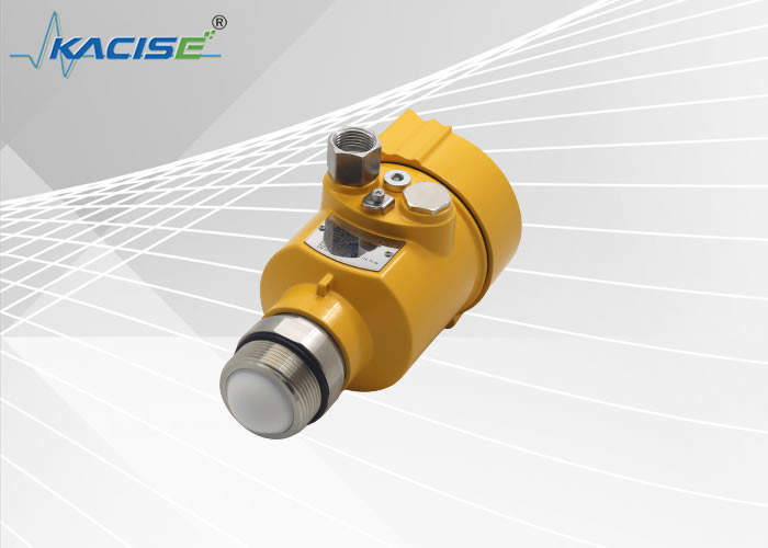
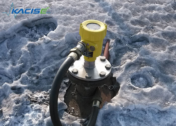
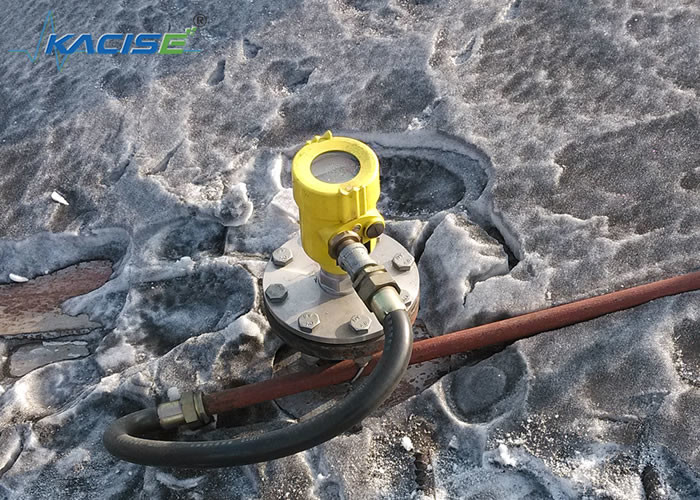
1. Product Overview
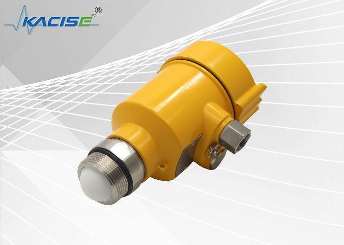
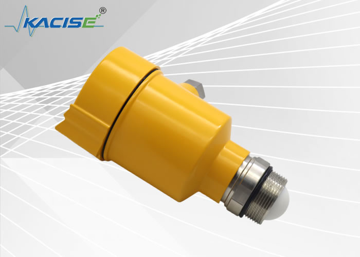
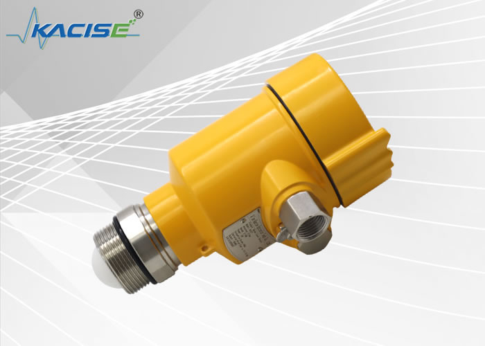
KLD80 series products are frequency modulated continuous wave (FMCW) radar products operating at 76-81GHz, supporting four-wire and two-wire applications. There are multiple models, the maximum range of the product can reach 120m, and the blind area can reach 8cm. Because of its higher operating frequency and shorter wavelength, it is especially suitable for solid-state applications. The working method of transmitting and receiving electromagnetic waves through a lens has unique advantages in high dust and harsh temperature environments (+200°C). The instrument provides flange or threaded fixing, which makes the installation convenient and easy.
The main advantages of KLD80 series FM radar level meter are as follows:
- Based on the self-developed CMOS millimeter-wave radio frequency chip, it realizes a more compact radio frequency structure, a higher signal-to-noise ratio, and a smaller dead zone.
- The 5GHz operating bandwidth enables the product to have higher measurement resolution and measurement accuracy.
- The narrowest 3° antenna beam angle, the interference in the installation environment has less impact on the instrument, and the installation is more convenient.
- Shorter wavelengths and better reflection properties on solid surfaces.
- Support remote debugging and remote upgrade, reduce waiting time and improve work efficiency.
- Support mobile phone Bluetooth debugging, convenient for on-site personnel maintenance work.
Communication and debugging
The instrument can be debugged through LDM in the field, and can also be debugged on the PC side with the optional host computer software. The connection between the meter and the PC is as follows:
to communicate with:
1. USB to RS485 serial cable (four-wire system);
2. USB to TTL serial cable (two-wire system);
3. USB to Hart-modem (two-wire system) for communication.
4. Through the mobile phone Bluetooth debugging, the on-site debugging is safer and more convenient.
5. 4G network, remote debugging through remote module.
2.Product Introduction
 |
Model KLD801
Application liquid, weak corrosive liquid
Measuring range 0-10m
Process connection thread/flange
Antenna size 22mm lens antenna
Accuracy ± 2mm
Protection grade IP67
Explosion proof grade Exd IIC T6 Gb
Frequency 76-81GHz
Power supply two wire/four wire/six wire system (DC24V/AC220V)
Signal output 4~20mA/HART/RS485 Modbus
Display/programming programmer with Bluetooth/5G remote network debugging
|
3.Technical Specifications
| Transmission Frequency |
76GHz~81GHz |
| Measuring Range |
0~120m (liquid) |
| Measurement Accuracy |
±2mm |
| Beam Angle |
3°/6° |
| Range Of Dielectric Constant Used |
≥2 |
| Power Supply Range |
DC24V/AC220V
2-wire system/4-wire system/6-wire system
|
| Communication Mode |
MODBUS bus
HART
|
| Signal Output |
4~20mA+RS485
4~20mA
|
| Fault Output |
3.8mA, 4mA, 20mA, 21mA, hold |
| Field Operation/Programming |
128 × 64 dot matrix display/4 buttons
can be equipped with host setting software
|
| Industrial Temperature/Humidity |
T0:-40~85℃/≤95%RH;T1:-40~200℃;
T2:-40~500℃; T3:-40~1000℃
|
| Shell Material |
Cast aluminum, stainless steel |
| Antenna Type |
Lens antenna |
| Process Pressure |
-0.1~2.5MPa |
| Cable Entry |
M20 * 1.5 or 1/2NPT |
| Recommended cable |
AWG18 or 0.75mm ² |
| Degree of protection |
IP67 |
| Explosion proof grade |
Exd IIC T6 Gb |
| Installation method |
Thread or flange |
| Net weight/gross weight |
Random configuration |
| Packing box size |
Random configuration |
| Transmission frequency |
76GHz~81GHz |
4.Structural dimensions
Schematic Diagram of Pipe Thread Process Connection Structure Size at Room Temperature
5. Installation
Two points for installation:
(1) Align the target material level to ensure that it is perpendicular to the material level plane;
(2) Avoid false echoes. See the following points for typical working conditions.
● Ensure that there are no interfering objects, such as ladders and steps, within the beam range.
Figure 5 – 1 Schematic Diagram of Instrument Installation Position
● The instrument installation shall ensure that the antenna beam avoids the feed inlet, as shown in Figure 5-2.
Figure 5 – 2 Antenna beam avoiding feed inlet
● The instrument shall be installed at least 20cm away from the vessel wall, otherwise it is likely to produce wrong readings, as shown in Figure 5-3.
Remarks: The liquid measurement installation spool should be perpendicular to the ground.
Figure 5 – 3 Installation at least 20cm away from the vessel wall
● The solid cone container shall ensure that the beam is directed at the tank bottom as much as possible, otherwise the measurement results at the tank bottom may be inaccurate, as shown in Figure 5-4.
Figure 5 – 4 The conical tank shall ensure that the beam is directed at the tank bottom as far as possible.
6. Product wiring diagram
6.1 Wiring diagram of single chamber enclosure 24VDC power supply four wire products
Fig. 6-1 Wiring Diagram of Four wire Products
In four wire system application, 4-20mA analog output is two separate terminals except 24V power supply terminal. At the same time, the four wire system also provides 485 output terminals, which is convenient for connection and debugging with PC or the site requiring 485 interface.
6.2 Wiring diagram of single chamber enclosure 24VDC power supply two-wire product
Fig.6-1 Wiring diagram of two-wire products
In the two-wire system application, in addition to the traditional power supply terminal (4-20mA output), the instrument also has a serial communication terminal, which is convenient to connect with the current mainstream IOT equipment or transparent transmission equipment for remote control and debugging.
Model Selection Table
80GHz FM radar level meter
| Model |
Model KLD801 |
| Licence |
P Standard type (non explosion proof)
I Intrinsically safe(Exia IIC T6 Ga)
D Flameproof type(Exd IIC T6 Gb)
|
| Process connection |
G 1 ½threads
A Flange DN50/304
B Flange DN80/304
C Flange DN100/304
D Flange DN125/304
E Flange DN150/304
Y Special customization
|
| Antenna type/material |
P 22mm Lens antenna
Y Special customization
|
| Process temperature |
V Standard/(-40~120℃)
Y Special customization
|
| Electronic unit |
2 (4-20)mA/24V DC Two wire
3 (4-20)mA/24V DC/HART Two wire
4 (4-20)mA/220V DC Four wire
5 RS485/Modbus/24V DC Four wire
6 (4-20)mA/RS485 /24V DC Six wire dual output
|
| Enclosure/degree of protection |
L Aluminium/IP67 Single cavity
B Aluminium/IP67 Double cavity
J stainless steel 304/IP68 Single cavity
|
| Cable incoming line |
M M20*1.5
N ½NPT
|

 Your message must be between 20-3,000 characters!
 english
 français
 Deutsch
 Italiano
 Русский
 Español
 português
 Nederlandse
 ελληνικά
 日本語
日本語
 한국
한국
 العربية
 हिन्दी
 Türkçe
 indonesia
 tiếng Việt
 ไทย
ไทย
 বাংলা
বাংলা
 فارسی
فارسی
 polski