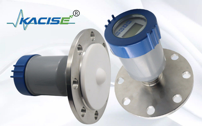
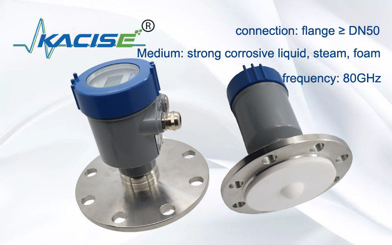
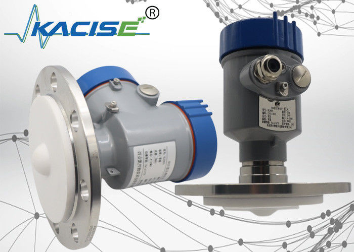
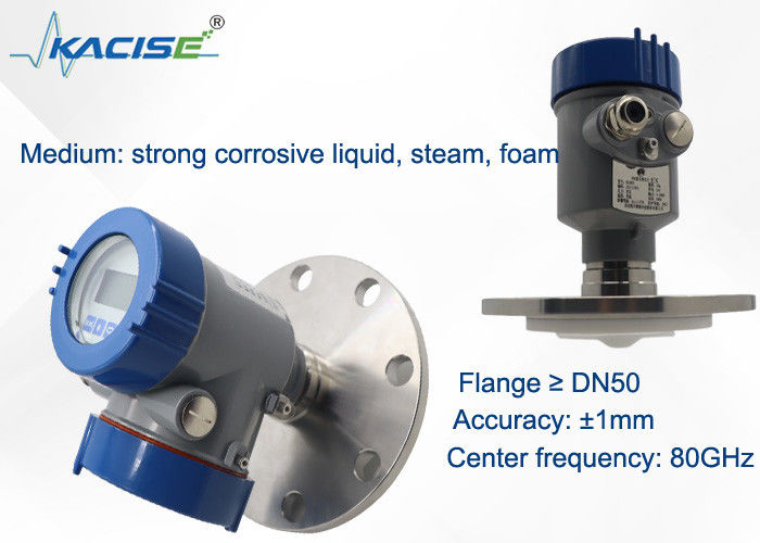
Kacise RS485 Radar Level Transmitter 80G Adjustable Frequency Radar Level Sensor 100m OEM

The Kacise RS485 radar level transmitter is an outstanding and highly advanced device designed for precise level measurement. With its 80G adjustable frequency radar level sensor, it offers remarkable flexibility and accuracy. This sensor can be fine - tuned to adapt to different application scenarios, ensuring optimal performance in various environments.
The transmitter is equipped with an RS485 interface, enabling seamless communication with other control systems. It allows for easy integration into existing industrial automation setups, facilitating efficient data transfer and remote monitoring. The ability to measure up to a 100m range makes it suitable for a wide range of storage tanks and vessels, whether in the chemical, oil, or water treatment industries. As an OEM product, it provides manufacturers with the opportunity to customize and integrate it according to specific project requirements, enhancing the overall functionality and compatibility of the level measurement solution. The robust construction of the device ensures reliable operation even in harsh and challenging conditions, providing long - term and stable level sensing capabilities.
1. Product Dimension
2. Working Principle
The radar antenna transmites narrow microwave pulse which will be reflected back when reaching the surface of the medium tested and then received again by the antenna system. The signals shall be transmitted to the electric circuit and then converted into level signals. As the transmission speed of microwave is so fast, the time used for the microwave transmission to the surface of the medium tested and then reflected back is almost 0.
3. Technical Features
- Millimeter wave radar, the measurement accuracy can reach up to ±2mm, and the minimum measurement blind zone is 0.05m.
- The smaller antenna size satisfies the measurement of more working conditions.
- A variety of lens antennas, smaller launch angles, more concentrated energy, stronger echo signals, and higher reliability than other radar products under the same industrial and mining conditions.
- It has stronger penetration and can be used normally in the case of adhesion and condensation.
- The dynamic signal range is larger, and the measurement of low dielectric constant media is more stable.
- Multiple measurement modes, radar response in fast measurement mode
4. Technical Specification and Model Selections
| Model |
KLD803 |
| Medium |
strong corrosive liquid, steam, foam |
| Measuring range |
0.1m~10/20/30/60/100m |
| Process connection |
flange ≥ DN50 |
| Process temperature |
-40~130℃
|
| Process pressure |
-0.1~2.5 MPa |
| Antenna size |
34mm lens antenna (according to flange size) |
| Antenna material |
PTFE |
| Accuracy |
±1mm (range below 35m) ±5mm (range between 35m and 100m) |
| Protection class |
P67 |
| Center frequency |
80GHz |
| Launch angle |
3° |
| Power supply |
Two-wire /DC24V / four-wire /DC12~24V / four-wire /AC220V |
| Casing |
aluminum/stainless steel |
| Signal output |
two-wire /4...20mA/HART protocol four-wire / 4...20mA/ RS485 Modbus |
5. Installation Requirements
When installing the instrument, avoid installing it above the material inlet, and try to avoid various objects that affect the signal, such as stirringpaddles, etc.
6. Electrical Connection
Power Supply
(4~20) mA/HART(2 wire)
The power supply and the output current signal share a two-core shielded cable. Please refer to the technical data for the specific supply voltage range.
(4~20) mA(4 wire/6 wire)
The power supply needs to be powered separately, and a four-core shielded cable is used for the power supply and current signal (the current signal and the RS485 interface can be output at the same time, and a six-core shielded cable is required for simultaneous output).
RS485/Modbus
The power supply needs to be powered separately, and a four-core shielded cable is used for power supply and digital signal. (The current signal and the RS485 interface can be output at the same time, and a six-core shielded cable is required for simultaneous output).
7. Connection
8. Safety Guide
Please observe the requirements of the local electrical installation regulations! Follow local regulations for personnel health and safety. All operations on the electrical components of the instrument must be completed by professionals who have received formal training. Please check the nameplate of the instrument to ensure that the product specification meets your requirements. Please ensure that the power supply voltage is consistent with the requirements on the nameplate of the instrument.
9. Grade of Protection
This instrument fully meets the requirements of protection class IP66/67, please ensure the waterproofness of the cable sealing head. As shown below:
How to ensure that the installation meets the requirements of IP67:
- Make sure the sealing head is not damaged.
- Make sure the cable is not damaged.
- Please make sure that the cables used meet the requirements of the electrical connection regulations.
- Before entering the electrical interface, bend the cable down to ensure that water will not flow into the housing, see ①
- Please tighten the cable gland, see ②
- Please plug the unused electrical interface with a blind plug, see ③
10. Sensor linearity
Beam Angle
The beam angle is the beam angle at which the energy density of the radar wave reaches half of its maximum value (3dB width). Microwaves emit signals out of beam range and can be reflected by interfering objects.
| Lens Antenna Diameter |
Φ32mm
lens Antenna
|
Φ42mm
lens Antenna
|
Φ76mm
lens Antenna
|
Φ74.7mm
lens Antenna with air purge
|
| Beam Angle |
7° |
6° |
3° |
3° |
The larger the antenna size and the smaller the beam angle α, the less interference echoes will be generated.
For more accurate measurements, avoid installing any internal devices (such as limit switches, temperature sensors, bases, vacuum rings, heating coils, baffles, etc.) within the range of the signal beam.
KLD800 series product show


 Your message must be between 20-3,000 characters!
 english
 français
 Deutsch
 Italiano
 Русский
 Español
 português
 Nederlandse
 ελληνικά
 日本語
日本語
 한국
한국
 العربية
 हिन्दी
 Türkçe
 indonesia
 tiếng Việt
 ไทย
ไทย
 বাংলা
বাংলা
 فارسی
فارسی
 polski