Product Description:

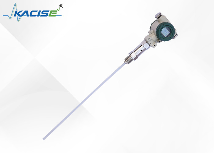
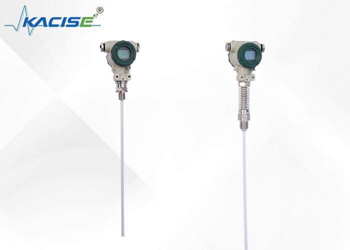
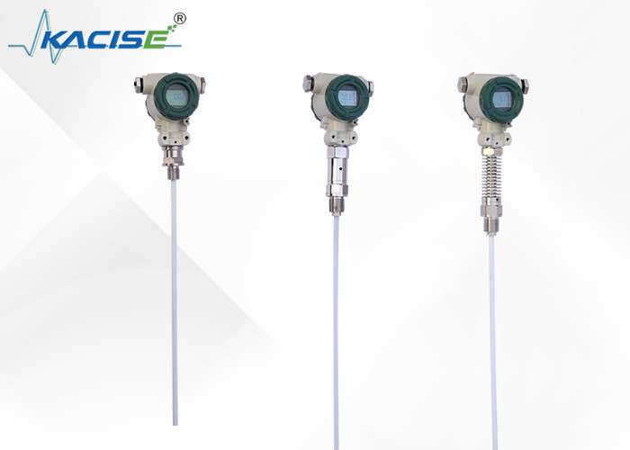
The KCF600 series capacitive level transmitter is an ideal solution for continuous detection of various liquids under harsh conditions, such as high temperature and pressure, high corrosion, tendency to crystallize, and easy plugging. It is especially suitable for measuring water, acid and alkali solutions, as well as water levels in boilers. The transmitter incorporates no moving or flexible parts, offering high reliability, easy installation, and excellent impact resistance at a reasonable cost. Additionally, it can replace traditional float, input, and differential pressure-based level transmitters in various situations.
The key components of the transmitter utilize advanced RF capacitive sensing which are precisely temperature-compensated and linearity-corrected. These components are then transformed into a standard electrical signal, usually within the 4-20mA range. The system is configurable with communication protocols such as HART, CANBUS, and 485. The transmitter features self-calibration across its full range, which enables automatic calibration of "zero" and "range" with just two key presses, offering adaptability to various complex situations.
Features:
Simple structures, without any movable or elastic components, have high reliability and require minimal maintenance. These instruments do not require regular medium and small repairs under normal circumstances.
A variety of signal output options are available to facilitate different system configurations.
The instruments are convenient for use in high temperature and high pressure containers. The measured data is not affected by the temperature, specific gravity, or shape of the container, or the pressure.
These instruments are especially suitable for measuring acid, alkali, and other corrosive liquids.
The instruments have perfect protection against overcurrent, overvoltage, and power polarity.
Technical Parameters:
●Detection range: 0.01~30 m
●Accuracy: level 0.2, level 0.5
●Pressure range: -0.1MPa~32MPa
●Probe temperature: -50~250 ℃
●Ambient temperature: -20~60 ℃
●Storage Temperature: -55℃~+125 ℃
●Output signal: 4~20mA,4 ~ 20mA with HART communication/485/CAN bus communication
●Supply voltage: 12~28VDC (should be powered by the safety barrier)
●Fixation: Screw mounting M20×1.5,M27×2,Flange mounting DN25,DN40,DN50.Special specifications can be customized
●Wetted material: 316 Stainless steel,1Gr18Ni19Tior or PTFE
●Long-term stability: ≤0.2%FS/Year,
●Temperature drift:≤0.02%FS/℃ ( range of 0~70℃)
●Explosion levels: Intrinsically Safe ExiraⅡC T6, Flameproof Ext II C T5
●Protection:IP67
●Intrinsically Safe parameters:Ui:28VDC,Ii:93mA, Pi: 0.65W, Ci: 0.042uf, Li: 0mH
Electronic interface and signals definition
Transmitter is a standard second-tier or three-wire instruments, The terminals of power (signal) located in the wiring side of the instrument inside housing, the signal line should be shielded cable or twisted pair , try not to line together with the other power cord tube or the next trough, nor through nearby the high-power equipment.
Picture1: Standard level transmitter wiring diagram
①Empty pin
②4-20mA+
③4-20mA-
④Empty pin
Two-wire connection
①Signal output
②24V power supply
③Common ground
④Empty pin
Three-wire connection
Picture2: HART communication transmitter wiring diagram
Picture3: Intrinsically safe wiring diagram
Installation
The cable and rod level transmitter has a variety of fixed ways to adapt to different site conditions. When the site cannot provide the process facilities such as the M20 × 1.5 female thread or flange, you can choose three methods of installation (wall-mounted, horizontal pipe rack and vertical tube rack, which make you handy in the on-site installation.(With pictures)
When measuring the media of the larger mobility, the user can choose the weight attachment in order to prevent the sensor form violent swing, which can play the role of the stability of the sensor. The heavy objects must be put into the bottom of the container when adding weight, so as not to break the sensor’s wire.
When the site conditions are bad, the user should use the sensor shield to protect the sensor in order to avoid foreign body damage or affect the measurement accuracy.
If the containers are not metal, we need to put the transmitter enclosure with a wire access to the bottom of the container when using a KCF600 rod level transmitter; otherwise the measurement is not accurate.
This product has been calibrated at the factory; he need for field adjustment may take the following methods:
A: Intelligent circuit debugging method:
Site-zero----- When the liquid level is located in the lowest place, holding down the "Z" key and "S" key for 8 seconds after the same time release, and then "Z" key click, the output current is automatically adjusted to 4mA.
Site - filled ------ When the liquid level at the highest place, holding down the "Z" key and "S" key for 8 seconds after the same time release, and then "S" key click ,the output current is automatically adjusted to 20mA.
B: Analog circuit debugging method:
When the liquid level in the next limit, use the screwdriver slowly rotating "Z" potentiometer, observe the ammeter readings close to 4mA
When the liquid level in the upper limit, use the screwdriver slowly rotating "S" potentiometer and observe the ammeter readings close to 20mA
And operate it for 2-3 times more, until the zero and span were accurate 4mA and 20mA. After adjustment, tighten the cover of the transmitter should be.
Note:
1. Products supply with product certification and manual, which have product number, technical parameters, wiring diagram, and the date of manufacture, please check to avoid the mistake.
2. The installation should be based on the product connection and thread types, check the site interface is consistent with the product interface or not. Tighten the threaded connection slowly, pay attention to sealing, the torque cannot be directly added to the transmitter housing and can only be added to the six-party transmitter interface.
3. Wiring should be strictly in accordance with company instructions.
4. This product is a precision Energy conversion instrument, prohibit disassemble, collision, fall and hard rejection to play.
5. Transmitter Work immediately after power on, but output could be stability after warming up for 30 minutes.
6. Abnormal use ,turns off the power, check, or contacts our technical department directly.
7. Transportation, storage should be to restore the original packaging and stored in a cool, dry, ventilated warehouse.
8. The installation process should pay attention to avoid the breaking of the skin of the sensor wire.
9. When installing the sensor wire, the distance from pool wall should be at least 10CM above, otherwise the measurement would be not accurate.
10. The grounding line of the whole PTFE structure and the rod level must be conduct with
measured media; otherwise the measurement would be not accurate.
11. The installation site should take effective lightning protection measures.
12. The enclosures of any transmitter in this series must be grounded; grounding resistance should be less than 4Ω.
13. Safety barrier should be made explosion-proof certification; its installation requirements should follow the requirements of instructions.
14. When the transmitter is used to "0" zone to the barrier-powered power transformers must meet the requirements of GB3836.4-2000 NO. 8.1.
Applications:
The Kacise Fluid Level Meter is suitable for a wide range of applications, including fuel level monitoring in GPS tracking solutions. It is powered by a power supply voltage of 2~28VDC and should be powered by the safety barrier to ensure safe and reliable operation. The probe temperature range is -50~250 ℃, and the pressure range is -0.1MPa~32MPa, making it ideal for use in a variety of industrial settings.
The Kacise Fluid Level Meter has an output signal of 4~20mA,4 ~ 20mA With HART Communication/485/CAN Bus Communication, making it compatible with a wide range of industrial control systems. It is easy to install and has a minimum order quantity of 2 units. The product is packaged in a carton and has a delivery time of 5 working days.
The Kacise Fluid Level Meter is a highly versatile product that can be used in a variety of scenarios. It is commonly used in truck and industrial tanks to monitor fuel levels, ensuring that the tanks are never empty and preventing costly downtime. It is also used in GPS tracking solutions to monitor fuel consumption and ensure that vehicles are operating at optimal efficiency.
In summary, the Kacise Fluid Level Meter is a high-quality product that is suitable for a wide range of industrial applications. It is a capacitance fuel level sensor that is easy to install, accurate, and reliable. Whether you need to monitor fuel levels in a truck or an industrial tank or are looking for a capacitance level detector for use in GPS tracking solutions, the Kacise Fluid Level Meter is an excellent choice.
Packing and Shipping:
Product Packaging:
- 1 Fluid Level Meter
- Instruction Manual
- Protective Case
Shipping:
- Ships within 7 business days
- Standard shipping rates apply
- Tracking information will be provided

 Your message must be between 20-3,000 characters!
 english
 français
 Deutsch
 Italiano
 Русский
 Español
 português
 Nederlandse
 ελληνικά
 日本語
日本語
 한국
한국
 العربية
 हिन्दी
 Türkçe
 indonesia
 tiếng Việt
 ไทย
ไทย
 বাংলা
বাংলা
 فارسی
فارسی
 polski