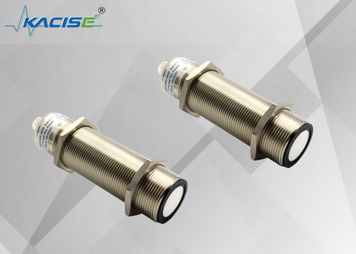
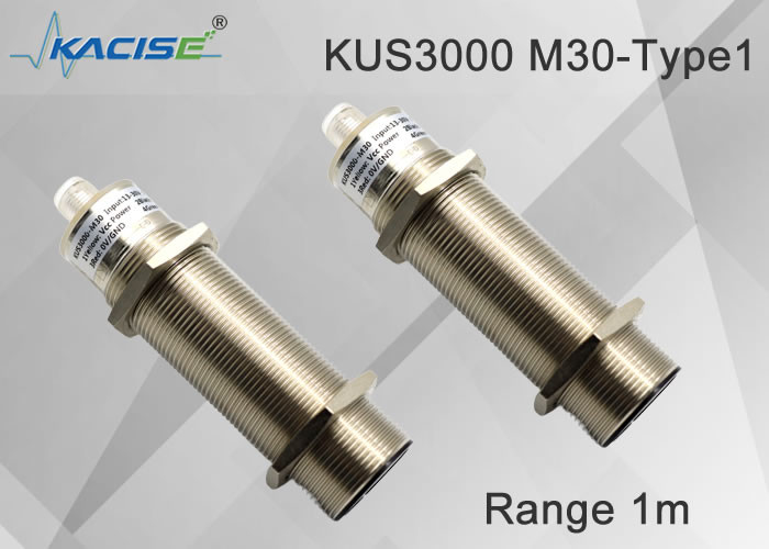
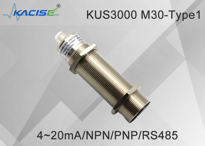
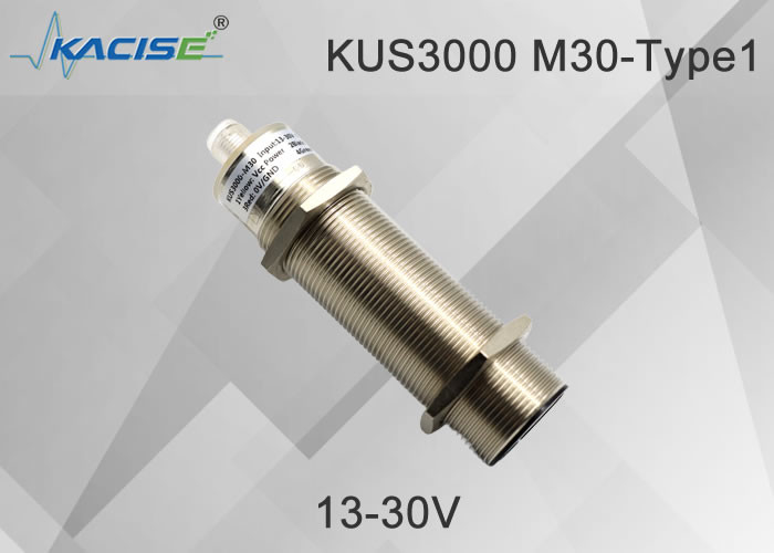
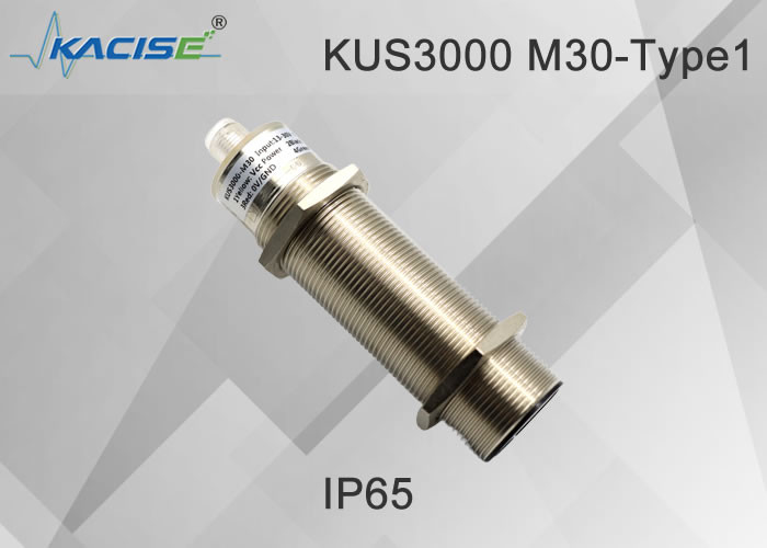
KUS3000 M30-Type1 Ultrasonic Level Meter

1.Feature
- High repeatability
- compact case
- non-contact detection;
- Not affected by object color and transparency; not affected by external environmental conditions, reliable solution;
- Works well in extreme conditions; able to be used in dark environments; low current consumption;
- The built-in anti-jamming smart chip has a fast frequency response, and the brass nickel-plated shell is flame-retardant, waterproof and oil-proof;
- The LED working indicator light is easy to use.
- The ABS induction probe and connectors are seamlessly connected with the equipment in various ways.
2. Dimensional structure
The unit is mm.
3. Electrical interface
Note: This product has two cable specifications, and the cable wiring instructions of the two specifications are as follows:
| Type A cable |
Type B cable |
| Pin1 |
Brown |
Pin1 |
Yellow |
| Pin2 |
White |
Pin2 |
Black |
| Pin3 |
Blue |
Pin3 |
Red |
| Pin4 |
Black |
Pin4 |
Green |
The default cable mix is based on the specifications received by the customer
4. Technical parameter
| M30-type 1 |
| Range |
200... 2000 mm |
| Adjustable interval range |
200….2000mm |
| Blind spot |
0 ... 200 mm |
| Response time |
approx. 10 ms |
Indicator light
| Blue led light |
The blue light flashes to indicate that calibration can be performed. Blue and other constants indicate that the power supply of the sensor is normal. The blue light will flash within 5 minutes after the power is turned on, indicating that the user can perform output adjustment and calibration. After 5 minutes, the blue light is always on to indicate that the sensor cannot be receiving Calibration command. . |
| Tellow led light |
It is used to indicate whether the measured object is detected. During the calibration stage, the yellow light flashes to indicate that the current calibration state is locked, and it can be switched to the next calibration state. |
| Red LED light |
In normal working state, the red light is not on, and the red light is on to indicate that there is a fault.
During the calibration process, the flashing red light indicates that the sensor locks the current echo loss or infinity state, and the user can switch to the next calibration state.
|
Electrical parameters
| Supply voltage |
13 ... 30 V DC , Special wide voltage requirements can be customized |
| No-load current I0 |
≤ 45 mA |
IOT-spectric models
| Supply voltage |
3.3-12 DC , ripple 10 %SS |
| Power consumption I0 |
≤ 15 mA, sleep mode≤1mA, Serial wake up, |
Output
| Output type |
1 Switch output PNP output normally open and long closed can be calibrated
2 Switch output NPN output normally open and long closed programmable
3 Analog voltage output 0-10V programmable.
4 Analog 4-20mA output programmable
5 RS485 output E4 programmable.
|
| Overcurrent Ie |
200 mA , Reverse polarity protection, short circuit protection |
| Default setting |
M18 Switch point A1: 150mm Switch point A2: 1000mm
M30 Type 1 switch point A1 200mm switch point A2: 2000mm
M30 type 2 switch point A1 300mm switch point A2: 4000mm
M30 type 3 switch point A1 500mm switch point A2: 6000mm
|
| Output voltage drop |
≤ 2.5 V |
| Repeatability |
≤1 % |
| On-off level f |
≤ 13 Hz High frequency can be customized |
| Default hysteresis characteristic amplitude |
5% of the set value, special requirements can be customized |
| Temperature Compensation Range |
-40℃-85℃ |
Temperature Requirements
| Working temperature |
-25…70℃(248...343K) |
| Storage temperature |
-40…85℃(233...358K) |
Mechanical part description
| Even machine |
V1 connector(M12×1),4-Pin |
| Protection class |
IP65 Other can be customized |
| Shell material |
Nickel-plated copper, others can be customized |
Note: When the M18 product and M30 product have 4-20mA analog output, the meter connection method is different from that of the 550,600 product. Since the output terminal of the M18 and M30 products is powered by VDD, as shown in Figure 1, the meter should be connected to the power supply port. Between the output terminal and the output terminal, the connection instruction diagram is shown in Figure 2:
Figure 1 Output power supply circuit diagram
Figure 2 Schematic diagram of connection method
5. Sensor function description
Switch point and advance interval setting and adjustment of switch output and analog output products
Switch value and analog output can be set using the adjustment terminal, specifically, there are 8 working modes that can be set.
The specific setting method of each type of bean flour is the following steps.
In the first step, the user selects a distance set by himself, or puts the sensor into a lost wave state.
The second part, connect the calibration terminal to the power supply or GND, keep it connected until the yellow light flashes (if the wave is lost, the red light flashes).
In the third step, the user selects the second distance set by himself, or lets the sensor enter the lost wave state.
The fourth step, connect the calibration terminal to GND or power supply (the state is different from the second step), keep it connected until the yellow light flashes (if the wave is lost, the red light flashes).
There are 8 working modes of switch output
1. Window normally open mode (analog output products are in positive linear working mode or distance measurement mode).
2. Window normally closed mode (analog output product is in negative linear working mode or liquid level measurement mode).
3. Single point normally open mode.
4. Single point normally closed mode.
5. Single-point normally open mode with large hysteresis interval.
6. Single point normally closed with large hysteresis interval mode.
7. Whether to detect the normally open mode.
8. Whether to detect normally closed mode.
Description of RS485 output model products.
There are 3 working modes,
1: Automatic measurement mode, the sensor continuously measures the liquid level and distance, and the user can read the measurement results through the 485 interface at any time.
2: If the user does not initiate a 485 communication, the sensor will initiate a measurement and report the result.
3: Sleep mode, the product enters sleep mode, the user first wakes up the sensor through the 485 interface, and then initiates a measurement and obtains the result before the sensor sleeps again.
| Definition of LED indicator meaning |
| |
|
When calibrating |
During normal work |
| red light |
Bright |
error indication |
error indication |
| extinguish |
normal work |
normal work |
| flicker |
Indicates the status of the calibration station lock-on echo loss |
meaningless |
| Yellow light |
Bright |
---- |
detected object |
| extinguish |
------ |
The measured object is lost |
| flicker |
Instructs the calibration stage to lock the current position and can switch to the next calibration state |
The echo lost and echo detected states alternate. relatively critical. |
| Blue light |
Bright |
normal power supply |
normal power supply |
| extinguish |
Abnormal power supply |
Abnormal power supply |
| flicker |
Indicates that the user can calibrate the sensor at the current time |
meaningless |
6. Installation conditions
When installing, pay attention to protect the surface of the sensor to avoid injury. If you work in an environment with heavy volatile gas or dust and heavy condensation, you need to clean the surface of the sensor regularly to avoid sensitivity reduction or failure to work. The installation thread should not be over-tightened, which will cause the sensor to be pressurized and not work properly.
7. Order information
|
KUS
|
Types of |
Output |
Range |
Describe |
| |
M18 |
M18 housing, maximum measuring range is 1 meter |
| M30-Type1 |
M30 maximum measuring range is 2 meter |
| M30-Type2 |
M30 maximum measuring range is 3 meter |
| M30-Type3 |
M30 maximum measuring range is 6 meter, 8 meters can be customized |
| Customized |
Shell supports user customization |
| |
NPN |
output as NPN |
| PNP |
output as PNP |
| 10Vout |
The output is analog 0-10V, the power supply requirement is greater than 11V |
| 5Vout |
The output is analog 0-5V, the power supply requirement is greater than 6V |
| mAout |
The output is analog 4-20mA |
| RS485 |
The output is RS485 Modbus protocol, please refer to the software interface manual for specific description. |
| |
|
XXX mm |
The customer specifies the linear interval or switch interval, which can be set at the factory |
| KUS |
M30 |
RS485 |
2000mm |
|

 Your message must be between 20-3,000 characters!
 english
 français
 Deutsch
 Italiano
 Русский
 Español
 português
 Nederlandse
 ελληνικά
 日本語
日本語
 한국
한국
 العربية
 हिन्दी
 Türkçe
 indonesia
 tiếng Việt
 ไทย
ไทย
 বাংলা
বাংলা
 فارسی
فارسی
 polski